Building a Digital Twin of the iCub Humanoid Robot’s Head
By Mattia Fussi, Mattia Salvi, Michele Gesino, Ugo Pattacini, and Marco Maggiali, Istituto Italiano di Tecnologia (IIT)
Within the Istituto Italiano di Tecnologia (IIT), our team at the iCub Tech facility designs, develops, and builds the iCub open-source robotic platform. Standing at 1 meter tall, the humanoid iCub robot—which is currently in use at more than 50 research centers and institutes worldwide—features 53 degrees of freedom, including six in the head, three in the neck, and three in the eyes. The robot also has over 50 motors, as well as force-torque sensors and inertial measurement units. While our work largely focuses on electromechanical design and low-level control firmware, our colleagues in other research lines develop advanced, higher-level control software to support a diverse range of applications, including human-robot interfaces and robotic avatar systems.
The complexity of the iCub platform makes it difficult to validate design ideas before actually implementing them in hardware. In the past, for example, we’d create the design in a CAD tool and run high-level simulations in a 3D robotics simulator, such as Gazebo, which requires writing bespoke code to model complex dynamics. It wasn’t until we built the new design, ran tests with our control firmware, and manually tuned controller gains that we could see how the new design would perform. Many of the challenges we faced stemmed from the inability to run accurate, dynamic simulations using a realistic model of our robot’s mechanical design.
To address these challenges, our team recently validated a new approach in which we used Simulink® and Simscape™ to create a digital twin of the iCub robot’s head and neck (Figure 1). This model enabled us to automatically tune our control gains and achieve a significant improvement in trajectory tracking performance. Moreover, it makes it possible for us to account for precise placement of masses, easily introduce realistic nonlinearities, and accurately simulate the actuation system—capabilities that are crucial for designing reliable control algorithms that can be safely applied to our robots.
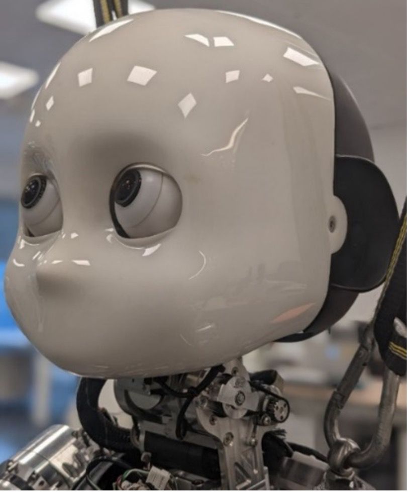
Figure 1. The iCub head with three degrees of freedom in the neck.
CAD Assembly Import and Model Linearization
To begin, we exported the neck assembly from our PTC® Creo™ CAD software to Simscape Multibody™ using the Simscape Multibody Link plugin (Figure 2). The plugin makes exporting the model from CAD very easy. Exporting the model yields a collection of geometry files—one per each rigid part—and one unique XML file containing information on how to assemble each part. This XML file is parsed by the smimport function, which automatically creates both a data structure defining all the model parameters and a Simscape Multibody block diagram with the data structure loaded in its model workspace. Starting with this imported baseline, we created accurate models of the neck’s cable differential system with Simscape Multibody and its transmission with Simscape Driveline™ (Figure 3).
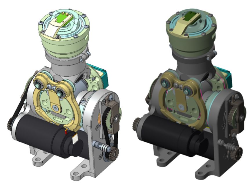
Figure 2. Models of the iCub neck mechanism in CAD software (left) and Simscape (right).
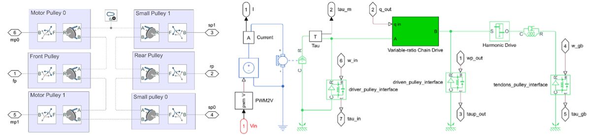
Figure 3. Cable differential (left) and outer transmission (right) models.
Next, we used the Model Linearizer app from Simulink Control Design™ to interactively linearize the Simscape model with the head placed vertically. After linearization, the model was composed of 38 states, which we subsequently reduced to 18 using the Model Reducer app from Control System Toolbox™.
Although we were able to create a stable controller for this model, we felt it was still overly complex. The linearization process had resulted in large matrices with numerous states that did not reflect the actual design well. This was due, in part, to the way we had built the CAD model. Some rigid elements in the model were not explicitly defined as such, resulting in additional degrees of freedom in the exported representation. To rectify this, we updated the assembly in PTC Creo, reducing complexity while keeping the dominant dynamics of the system intact. We then reimported the updated model into Simscape and ran the linearization process again. The result was a smaller, simpler, and more tractable model that made it easy for us to understand the frequency response and transfer functions. For example, we used Robust Control Toolbox™ to create uncertain linearized state-space models for both the pitch and roll joints. These models included uncertain parameters—for which we defined a range of possible values—and enabled us to identify a set of decoupled transfer functions (Figure 4). We ran the linearization process at three different operating points for each joint: with the head vertical, tilted fully to the minimum, and then to the maximum limit.

Figure 4. Frequency response of the system with uncertain parameters representing the decoupled pitch angle.
Improving Controller Tracking Performance
With a more accurate model of the iCub head and neck, we were ready to begin tuning the gains for the pitch and roll discrete proportional-integral-derivative (PID) controllers. We defined both soft and hard objectives for the tuning procedure, using the systune function from Control System Toolbox to tune the controller gains.
We had previously determined a set of gain values empirically based on multiple experiments with the physical head and neck assembly. The tuning process in Simulink revealed that we needed to increase the gains from these empirically determined values substantially. In particular, we needed an almost 30-fold increase in the integral gain, which is essential to compensating for the gravity acting on the head (Table 1).
Default Values |
Tuned Values |
|
| P (% / deg) | 9 |
Pitch 19.2 / Roll 16.3 |
| I (% / (deg · s)) | 3 |
Pitch 88.8 / Roll 85.7 |
| D (% / (deg / s)) | 0.2 |
Pitch 0.55 / Roll 0.46 |
Table 1. Original and tuned values for PID gains.
We tested the new gains in a basic controller model in Simulink using the Simscape plant model. For these tests, we had the head move through a series of waypoints in a minimum jerk polynomial trajectory that we generated with Robotics System Toolbox™ (Figure 5).
Figure 5. Animation of pitch and roll angle dynamics simulated in Simscape while tracking minimum-jerk trajectories.
Simulation results showed a remarkable improvement in trajectory tracking. For example, the root-mean-square error (RMSE) was reduced by more than 80% for pitch tracking and more than 75% for roll tracking. We then tested the new gain values on the iCub robot, with the results confirming the significant improvements in tracking error and simulation time that we observed in simulation (Table 2).
RMSE (deg) |
RMSE (deg) |
|
Pitch |
||
Simulation |
0.313 |
0.0587 |
Robot |
0.705 |
0.162 |
Roll |
||
Simulation |
0.129 |
0.0297 |
Robot |
0.450 |
0.122 |
Table 2. Simulated and measured RMSE for pitch and roll tracking for default and tuned gain values.
Validating Our Model and Our Approach
It was clear from simple visual observation that our Simscape model was providing an accurate representation of the real robot’s movements (Figure 6).
Figure 6. Real and simulated movement of the neck assembly.
To further validate the model, however, we performed a direct comparison of simulation and measured pitch and roll angles. We found little difference between simulation results and results from real-world tests (Figure 7).

Figure 7. Pitch and roll angles from simulation (blue) and on-robot tests (red).
Our success in improving controller performance with a process that can be employed before testing on physical hardware also validated our overall approach. We are confident that this methodology can be applied to other iCub limbs and components to build a complete digital twin of the robot. We’ve already applied this approach on another project for our ergoCub robot, ensuring that all performance requirements of the controller were met before the physical robot was available for testing.
Looking ahead, we are planning to add complex nonlinear effects—such as belt slack, pulley flattening, and friction—to our model and continuing to simulate the dynamics of new hardware features long before production. With the ability to accurately model and simulate physical phenomena, we are also positioned to begin performing predictive maintenance on our robot platforms in the future.
Published 2023