Developing a Multidomain Hypercar HVAC System Through Industry-Academia Collaboration
By Jordi Villar Venini, MathWorks, with Massimo Violante, Politecnico di Torino; Gianluca Aquaro, EMA Global Engineering; and Mirko Zanotel, EMA Global Engineering
Close collaboration between academia and industry not only helps students develop essential skills, but it also plays a crucial role in designing new systems, integrating them into innovative products, and bringing those products to market. This was certainly the case in a recent vehicle heating, ventilation, and air conditioning (HVAC) project completed through a collaboration between EMA Global Engineering, Politecnico di Torino, and MathWorks.
An Italian automobile manufacturer needed a controller for the HVAC system in its next-generation hypercars—multimillion dollar vehicles equipped with custom-built engines that are capable of rapidly accelerating to speeds over 230 mph (370 kph). The manufacturer engaged EMA Global Engineering to develop the control software based on the company’s extensive expertise in designing and developing systems for car makers targeting niche markets.
A key challenge—aside from the number of subsystems and inherent complexity of a modern vehicle HVAC system—was that development was to begin before the car or the HVAC system itself had been built. EMA Global Engineering CTO Mirko Zanotel viewed this challenge as an opportunity to expand his engineering team’s use of Model-Based Design—specifically, by using a physical model to simulate and optimize the controller well in advance of hardware availability.
Zanotel reached out to Professor Massimo Violante, who teaches courses featuring Model-Based Design at nearby Politecnico di Torino, to suggest a collaboration. Violante recommended that his graduate student Gianluca Aquaro develop a physical model of the vehicle HVAC system as part of a master’s thesis. Violante saw that all the ingredients for a successful collaboration were in place. “EMA Global had a well-defined problem that could be addressed via Model-Based Design,” he explained. “Aquaro was interested in completing his master’s thesis in this area in collaboration with a company and MathWorks was ready to provide any necessary support.”
Over the next several months, Aquaro used Simulink® and Simscape™ to develop a detailed model of the HVAC system that spanned six different physical domains: gas, thermal liquid, thermal, two-phase fluids, moist air, and mechanical. The model made it possible for EMA Global to calibrate, optimize, and realistically test the performance of the HVAC control system via simulation under a wide range of operating scenarios. This approach not only minimized the time need for testing on the hypercar itself, but it also shortened overall development time and put EMA Global in a position to respond rapidly to future change requests from the manufacturer—for example, to optimize the HVAC system and control parameters for vehicles operating in unusually hot or cold climates.
Jumpstarting Model Development with a Reference Example
When he began working on the project, Aquaro had experience with MATLAB® and Simulink from Professor Violante’s Model-Based Design course and other courses taken at Politecnico di Torino. However, he had relatively little experience with physical modeling and Simscape. To get started, Aquaro explored the vehicle HVAC system example included with Simscape that models moist air as it flows through a recirculation flap, a blower, an evaporator, a blend door, and a heater before returning to the cabin (Figure 1).
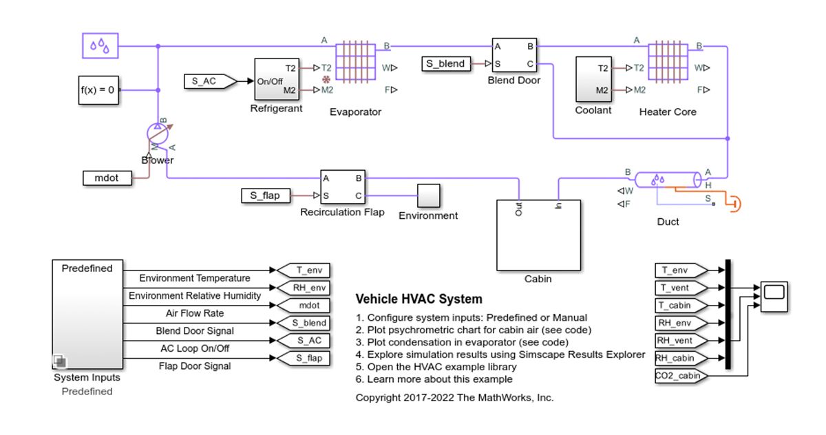
Figure 1. Example model of an HVAC system.
Even though it would need to be modified and extended to match the unique specifications of the hypercar, this model provided a vital jumping-off point for the thesis and the entire engineering effort. According to Violante, having the example model as a starting point was instrumental because it could easily take a student six months to develop such a model when starting from scratch, leaving no time to complete the actual thesis work.
Model Enhancements
Aquaro began updating the reference model, adjusting model parameters based on data sheets provided by the hypercar manufacturer for the blower, evaporator, compressor, ducts, and other components. He also extended and enhanced the model in several ways, incorporating additional physical domains and replacing individual subsystems with more detailed alternatives that more accurately reflected the dynamics of the components the manufacturer planned to use (Figure 2).
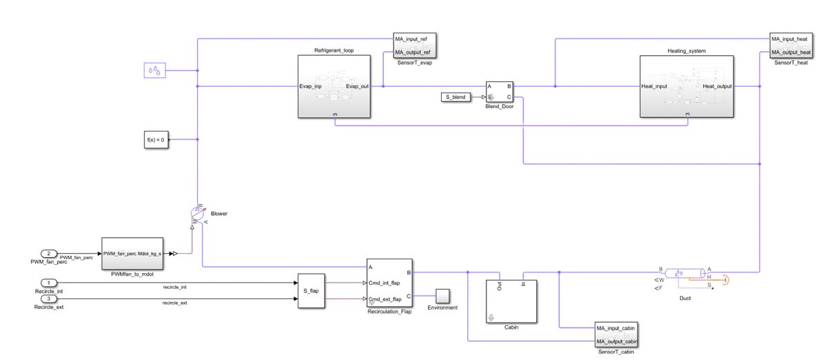
Figure 2. The completed top-level vehicle HVAC model.
The replacement of the evaporator block was one of the key modifications that Aquaro made to the original model. This block is used in the refrigerant cycle along with the compressor and condenser blocks (Figure 3). Aquaro replaced the block, which initially simulated the behavior of the evaporator based only on the refrigerant temperature as input, with a complete subsystem that accounts for cooling air inside the duct and uses the two-phase liquid domain to model the properties of the R-1234yf refrigerant used in the hypercar.
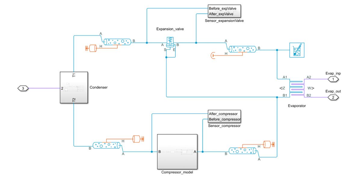
Figure 3. Model of the refrigerant cycle.
Implementing Modeling Guidelines and a Testing Framework
At Professor Violante’s encouragement, Aquaro adopted a variety of industry practices in developing the HVAC system model. For example, he followed MathWorks Advisory Board (MAB) modeling guidelines to increase the model’s readability and reusability, making it easier for other engineers at EMA Global to both understand how it worked and adapt it for other projects.
Aquaro also generated a set of test harnesses for running simulation-based tests of components in the HVAC system model. He generated these harnesses with Simulink Test™, which includes a test manager that Aquaro used to manage and execute tests of the model under a variety of scenarios (Figure 4). As part of the test plan, Aquaro created a simple control model in Simulink, which he then combined with the plant model he had developed in Simscape to create a system-level model for running closed-loop tests. Further, he used MATLAB and Simulink Projects to organize all of these models, along with tests and test results, in a single environment.
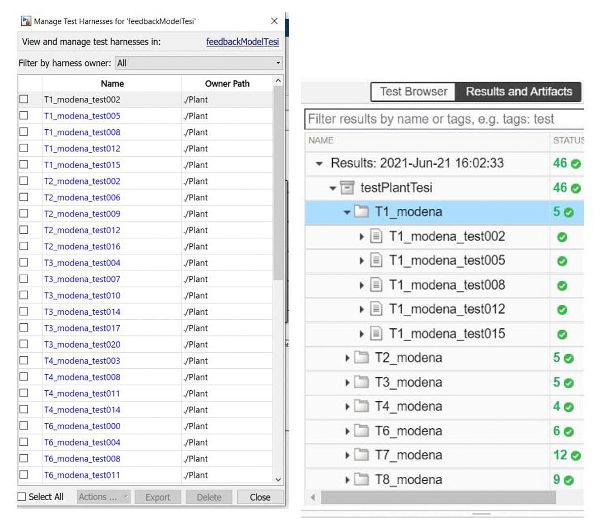
Figure 4. Test harnesses generated for a single component (left) and test results shown in the test manager (right).
As part of the workflow for testing the model, Aquaro ran numerous simulations focused on verifying the performance of the heat, refrigeration, and duct (airflow) subsystems. He then used MATLAB to postprocess and visualize the simulation results (Figure 5).

Figure 5. Visualization of R-1234yf refrigerant properties.
Vehicle Testing and Next Steps
When the hypercar manufacturer made a prototype vehicle available for testing, EMA Global engineers were ready to test the control design they had tuned based on the the Simscape model. With access to the car, Aquaro had the opportunity to compare the simulation results from the model to measured results from the actual HVAC system (Figure 6) and identify second-order effects that influence simulation accuracy—such as the effect of vehicle speed on the temperature of air in the ducts.

Figure 6. Comparision of measured and simulated temperatures for cooling (above) and heating (below) subsystems while the vehicle is moving.
EMA Global engineers fine-tuned their control parameters based on the results of these vehicle tests, and the control system is now running on an ECU in the production version of the hypercar. Upon receiving his master’s degree, Aquaro was hired by EMA Global to continue his work on the model and other Model-Based Design projects at the company.
Going forward, EMA Global can reuse the HVAC model on future versions of the hypercar by simply adjusting parameters as necessary in the Simulink model workspace (Figure 7).
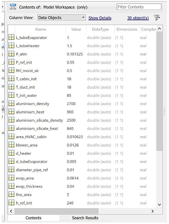
Figure 7. Modifiable HVAC system parameters in the model workspace.
Zanotel notes that, aside from the model itself, the entire approach used throughout the effort has the company well-positioned. “This project was a great opportunity for EMA Global to collaborate with both MathWorks and Politecnico di Torino in applying a state-of-the-art automotive engineering approach that we can now continue to use moving forward.”
Published 2023