Dynamic Inflow (Finite-State)
Libraries:
Aerospace Blockset /
Rotor Systems /
Rotor Aerodynamics
Description
The Dynamic Inflow (Finite-State) block computes the normal induced velocity through the rotor disc by solving a set of ordinary differential equations. The number of state variables depends on the number of harmonics and number of radial modes used in the computation. The model used in the block is developed from incompressible flow Euler equations with the rotor modeled as an actuator disc.
The Dynamic Inflow (Finite-State) block models the azimuthal variation of inflow using trigonometric functions and the radial variation using Legendre functions. The block also computes the induced velocity required for blade force and moment calculations with good accuracy while avoiding heavy computation. The method is designed for integration into flight-control and simulation architectures, providing a balance of fidelity and efficiency for analysis and real-time applications.
Note
This inflow model is based on potential flow equations and is designed for conditions where incompressible flow assumptions are valid. The block does not automatically monitor local Mach numbers or enforce incompressibility limits, allowing flexibility for a wide range of input parameters. For best results, it is recommended to verify that their operating conditions fall within the typical range for incompressible flow.
Ports
Input
Output
Parameters
To edit block parameters interactively, use the Property Inspector. From the Simulink® Toolstrip, on the Simulation tab, in the Prepare gallery, select Property Inspector.
Input and output ports and parameter units, specified as Metric
(MKS) or English.
| Units | Radius | Elemental Force Distribution | Density |
|---|---|---|---|
Metric
                (MKS)
| Meters | N/m | kg/m3 |
English (Velocity in ft/s)
| Feet | lbf/ft | slug/ft3 |
Programmatic Use
Block Parameter:
units |
| Type: character vector |
Values:
Metric (MKS) | English |
Default:
Metric (MKS) |
Source of the angular velocity of the rotor, specified as one of
Dialog or Port.
Programmatic Use
Block Parameter:
omegaSrc |
| Type: character vector |
Values:
Dialog | Port |
Default:
Dialog |
Rotational speed of rotor, specified as a real scalar in radians per second.
Dependencies
This parameter is visible when the Rotational Speed Source parameter is set to Dialog.
Programmatic Use
Block Parameter:
omega |
| Type: double |
Values:
41.2596 | real scalar |
Default:
41.2596 |
Rotor radius, specified as a nonzero scalar in m or ft. This is the distance from the center of the rotor hub to the tip of the rotor blades, specified by R in the equations for μ, μz and λi.
Dependencies
The unit of Blade radius depends on the value of the Units parameter.
Programmatic Use
Block Parameter:
radius |
| Type: double |
Values:
5.08 m | real positive scalar |
Default:
5.08 m |
Source of radial locations, specified as one of Uniform distribution based on force input or Custom distribution. This parameter determines how the radial positions along the rotor blade are specified for aerodynamic computations.
Uniform distribution based on force input- The entire length of the rotor blade is divided into equal segments based on the number of radial locations Nr specified in the force input. For example, if the number of columns in force input is 10, the blade span will be divided into 10 equal segments, as shown in the figure.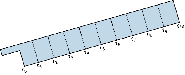
Custom distribution- You can specify non-uniform radial positions along the blade, using the parameter Non-dimensional radial element edges (default: -1 for uniform distribution).
Programmatic Use
Block Parameter:
radSrc |
| Type: char vector |
Values:
Uniform distribution based on force input |
Custom distribution |
Default:
Uniform distribution based on force input |
Custom radial segment limits (non-dimensional), specified as a real scalar (-1) or real nonnegative strictly increasing vector with values in [0 1]. The length of the vector should be one greater than Nr, the number of columns in the force input. It is expected that the input force values are computed or obtained at the mid-points of the radial segments specified through the parameter. For example, if the user inputs the parameter as, [r0 r1 r2 r3 r4 r5 r6 r7 r8 r9 r10], with r0>=0, and r10<=1, a sample blade segment distribution is as shown in the figure and Nr will be 10. It is expected than the range r0 to r10 is the aerodynamically effective region of the blade and the integration to compute force is done only in this region.
If this parameter is set to -1 (default value), uniform distribution approach is followed.
Dependencies
This parameter is visible when Radial locations source
is set to Custom distribution.
Programmatic Use
Block Parameter:
radDistr |
| Type: double |
| Values: real scalar | real nonnegative strictly increasing vector with values in [0 1] |
Default:
-1 |
Highest harmonic variation to be considered in the modeling of azimuthal variation of inflow through the rotor disc, specified as a non-negative scalar in the range [0,6].
Tips
When you increase the number of harmonics, you enhance model fidelity but also raise computational demands. Therefore, choose the number of harmonics to balance the need for accuracy with the limitations of computational resources.
Programmatic Use
Block Parameter:
indexHarmonic |
| Type: double |
Values:
2| nonnegative scalar |
Default:
2 |
Method to compute number of radial modes per harmonic, specified as one of
Consistently upgraded or Constant.
Programmatic Use
Block Parameter:
methodSpatialModes |
| Type: char |
Values:
Consistently upgraded| Constant |
Default:
Consistently upgraded |
Number of spatial modes per harmonic, specified as a real positive scalar.
Programmatic Use
Block Parameter:
numSpatialModes |
| Type: double |
Values:
2| real positive scalar |
Default:
2 |
References
[1] He, Chengjian. Development and Application of a Generalized Dynamic Wake Theory for Lifting Rotors. PhD diss., Georgia Institute of Technology, 1989.
[2] Peters, David A. “How Dynamic Inflow Survives in the Competitive World of Rotorcraft Aerodynamics.” Journal of the American Helicopter Society 54, no. 1 (2009): 011001.
Version History
Introduced in R2026a