Export Data to MATLAB
This example shows how to analyze the results of communications system simulations by using a To Workspace (Simulink) block to send model data to the MATLAB® workspace. You can process and analyze the data output to the workspace without rerunning the model.
Run System Simulation
In this example the cm_hammingcode model encodes data, passes it through a binary symmetric channel, decodes the data, and then computes and displays the error rate. The model includes four To Workspace blocks that output simulation results to a Simulink.SimulationOutput (Simulink) object, out. The out object contains the simulation signal data and results from all four To Workspace blocks. For details, see the information about the see Single simulation output (Simulink) model parameter.
From the MATLAB command line, open the model and run the simulation.
model = 'cm_hammingcode';
open_system(model);
out = sim(model);
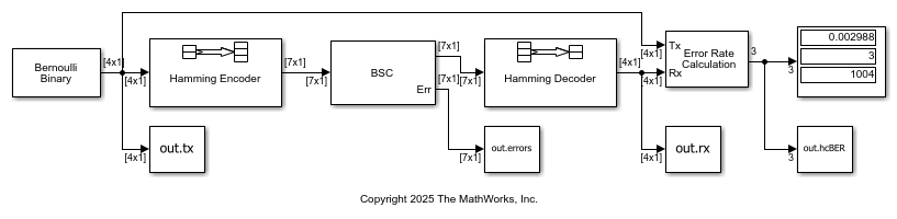
A Hamming Encoder block encodes the data before sending it through the channel. The default code is the [7,4] Hamming code, which encodes message words of length 4 into codewords of length 7. As a result, the block converts frames of size 4 into frames of size 7. The code can correct one error in each transmitted codeword. The model sends the error rate results (
out.hcBER), binary symmetric channel errors (out.errors), transmit data (out.tx), and decoded receive data (out.rx) to the workspace by using separate instances of the To Workspace block from the DSP System Toolbox™/Sinks library. This version of the To Workspace block preconfigures the block to output a 2-D array with each time step concatenated along the first dimension. For more information, see To Workspace Block Configuration for Communications System Simulations.
The Binary Symmetric Channel block has the Output error vector parameter selected so that it adds the
Errport to output error data for each data frame processed. You can analyze theErroutput to find any frames with more bit errors than the [7,4] code rate Hamming Decoder block can correct. This type of information can help you design a system to include forward error correction schemes to counter the prevailing channel conditions.The To Workspace block that outputs the
hcBERvariable has the Limit data points to last parameter set to1so that it outputs the final error rate calculation results only. The values output inout.hcBERmatch the final values shown by the Display block.The To Workspace blocks that output the
tx,rx, anderrorsvariables set the Save 2-D signals as parameter to3-D array (concatenate along third dimension)to partition these outputs in frames indexed by the third dimension.
View Error Rate Data in Workspace
After running a simulation, you can view the output of the To Workspace blocks. These commands print the Error Rate Calculation block output as a 1-by-3 vector, [error rate; total number of errors; total number of samples], in exponential form.
format short e
out.hcBER
ans =

   2.9880e-03   3.0000e+00   1.0040e+03
View Signal and Error Data in Workspace
After running a simulation, you can display individual frames of data. Becasue signals are typically large, displaying the entire transmit or receive signals is not practical.
The following command displays the sixteenth frame of channel errors as a column vector of length 7, corresponding to the length of a codeword. The out.errors output for the frame contains one 1, which means the channel introduced one error in the sixteenth frame.
out.errors(:,:,16)
ans =

     0
     0
     0
     1
     0
     0
     0
Since the channel introduced only one error in the sixteenth frame, the [7,4] code rate Hamming code can correctly decode the received signal data. Display the sixteenth transmitted and received frames to show that they match.
out.tx(:,:,16)'
out.rx(:,:,16)'
ans =

     0     1     0     0


ans =

     0     1     0     0
Analyze Signal and Error Data
You can use MATLAB® to analyze the data from a simulation. To analyze the error correction performance of the Hamming code, inspect the out.tx, out.rx, and out.errors workspace variables.
This command creates the vector of differences between the transmitted and received signals:
diffs = out.tx ~= out.rx;
The vector diffs is the XOR of the vectors out.tx and out.rx. A 1 in diffs indicates that out.tx and out.rx have at least one bit error in that frame.
To determine the indices of frames corresponding to message words that are incorrectly decoded, use the find command. The vector err_frame_idx records the indices where out.tx and out.rx differ. Frame 195 has three uncorrected bit errors for the default cm_hammingcode model configuration. Therefore, err_frame_tdx is a 3-by-1 vector with 195 repeated three times.
[~,err_frame_idx] = find(diffs)
err_frame_idx =

   195
   195
   195
To view the first incorrectly decoded message word, display the tx and rx data for the first error index and the corresponding frame from the errors output. The channel introduces two bit errors for the codeword which leads to an incorrect decoded message, which has three bit errors, when compared to the message.
if (err_frame_idx)
    out.tx(:,1,err_frame_idx(1))'
    out.rx(:,1,err_frame_idx(1))'
    out.errors(:,1,err_frame_idx(1))'
    numframe_err = find(sum(out.errors(:,1,:))>1)'
end
ans =

     0     0     1     1


ans =

     1     1     1     0


ans =

     0     0     0     0     1     0     1


numframe_err =

   195
To explore further, change channel errors by changing the Initial Seed or Error probability parameter values in the Binary Symmetric Channel block. Analyze this data to determine the error patterns that lead to incorrect decoding.
See Also
To Workspace (Simulink)