Generate FMU for First-Order Low Pass Filter from C/C++ Code
This example shows how to integrate C/C++ code and generate a Functional Mock-up Unit (FMU) using the Code to FMU tool.
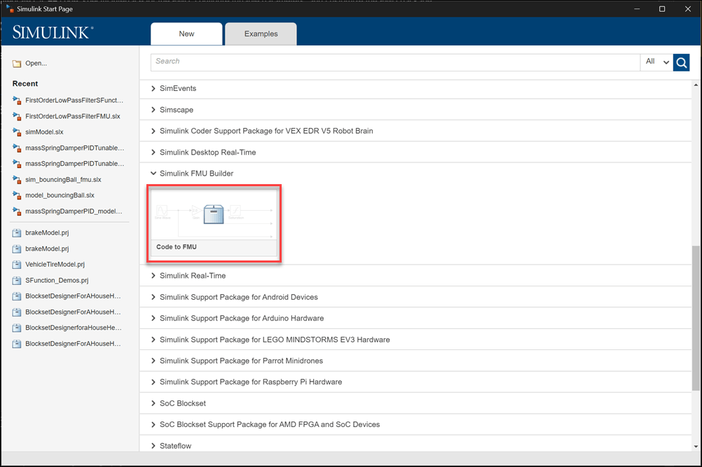
Create a new Code to FMU project or open an existing project. To create a new project, on the HOME tab of the MATLAB toolstrip, click Simulink. This opens the Simulink Start Page. Click Code to FMU from the Simulink FMU Builder section.
Doing so opens the Create Project dialog. Specify the name and folder for your project and click OK. This opens a project in MATLAB along with a blank Code to FMU window.
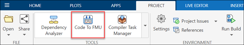
You can also open and access the Code to FMU window from the Project tab in the MATLAB toolstrip.

Integrate C/C++ Source Code into Code to FMU
Integrate a C++ class that defines a first-order low pass filter into the Code to FMU tool.
The filter is defined by the following equation,
,
where:
is the cutoff frequency
The filter can be represented in time domain using Tustin Bilinear transform as,
,
,
where:
and are the filter outputs at the current and previous time steps
and are the filter inputs at the current and previous time steps
is the sample time
Define the first-order low pass filter using C++ code.
class FirstOrderLowPassFilter
{
   private:
      double cutoffFrequency;
      double sampleTime;
      double previousOutput;
      double previousInput;

   public:
      FirstOrderLowPassFilter(double cutoffFrequency, double sampleTime);
      double computeFilterOutput(double input);
};
Define the methods.
#include "FirstOrderLowPassFilter.hpp"

FirstOrderLowPassFilter::FirstOrderLowPassFilter(double cutoffFreq, double SampleTime)
{
    cutoffFrequency = cutoffFreq;
    sampleTime = SampleTime;
    previousInput = 0.0;
    previousOutput = 0.0;
}


double FirstOrderLowPassFilter::computeFilterOutput(double input)
{
    double alpha = (3.14*cutoffFrequency*sampleTime);

    double output = ((1-alpha)/(1+alpha))*previousOutput + ((alpha)/(1+alpha))*(input + previousInput);

    previousOutput = output;
    previousInput = input;

    return output;
}
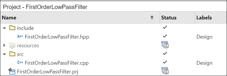
Create and organize these files into src and include directories in the project. To create a new folder in the project, right click on the project pane, select New and click on Folder. Create an include folder to store the header file and src folder to store the source file.
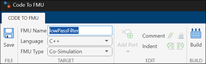
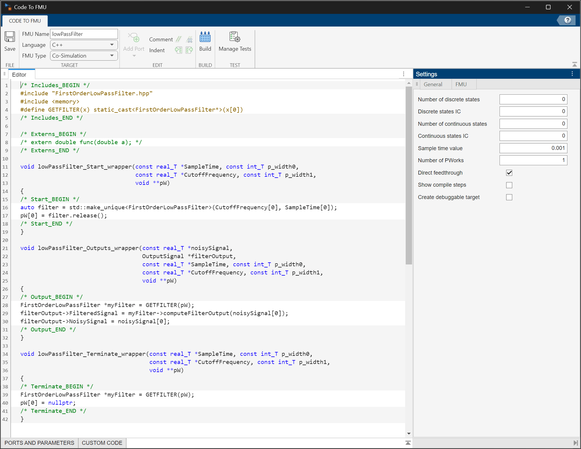
Open the Code to FMU window from the Project tab in the MATLAB toolstrip.
Specify the FMU Name, Language, and FMU Type in the CODE TO FMU toolstrip.
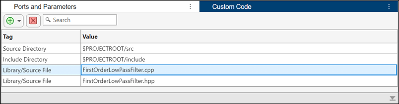
Add the library and source directories to the Custom Code table in the Code to FMU window. Click the ![]() button to add items to the table. Specify the source directory, source file, include directory, and library file.
button to add items to the table. Specify the source directory, source file, include directory, and library file.
Configure the input and output ports and specify desired tunable parameters for the FMU block. Configure a scalar input and a bus output for the FMU. Click the ![]() button to add these specifications to the Ports and Parameters table.
button to add these specifications to the Ports and Parameters table.
openProject('FirstOrderLowPassFilter');
OutputBusDefinition;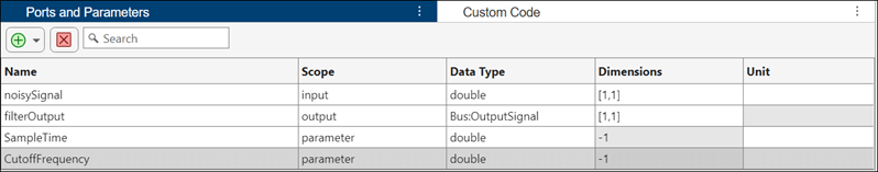
Specify General and FMU settings in the Settings pane.
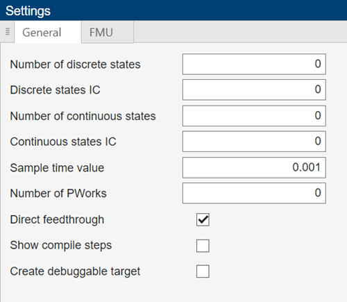
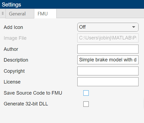
The code uses one PWork to store a pointer to the instantiated filter object. The FMU is configured to have one input and one output port. The input port receives the noisy signal. The output port is configured with a bus data type. The bus output signal gives the filtered and unfiltered signal. The sample time and cutoff frequency are set as parameters with units for the FMU.
Generate FMU
To the generate the FMU, click Build on the CODE TO FMU toolstrip.
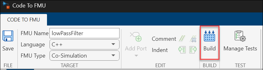
The generated FMU is stored in the buildOutput folder of the project.
openProject("FirstOrderLowPassFilter.prj");

filterProjObject = FMUBuilder.CodeToFMU('FirstOrderLowPassFilter.prj');
filterProjObject.build();
Generating 'lowPassFilter.fmu'. .... Please wait.
FMU 'lowPassFilter.fmu' created successfully.
Import and Simulate FMU in Simulink
Use the FMU Import block to import the generated FMU into a Simulink Model.
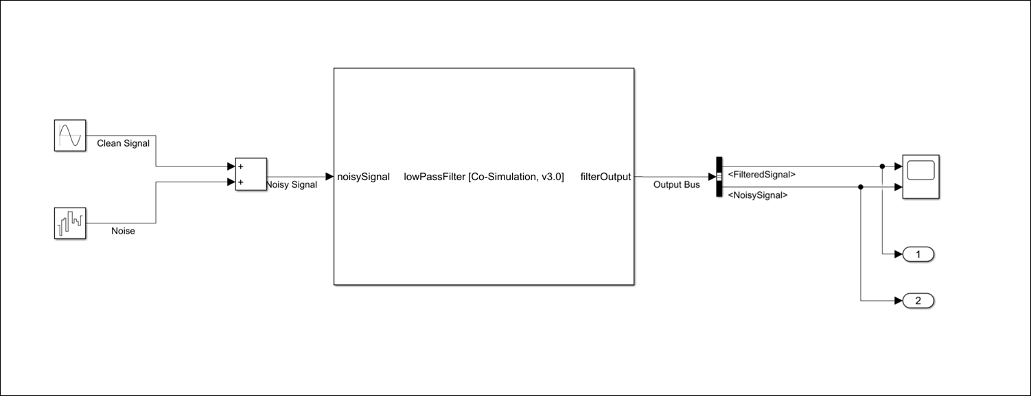
open_system("FirstOrderLowPassFilterFMU.slx");Open the FMU block dialog and check if the generated FMU has the same port, parameter, and unit configuration as specified in the Code to FMU editor.
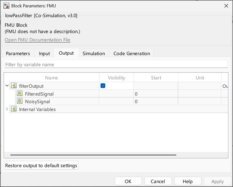
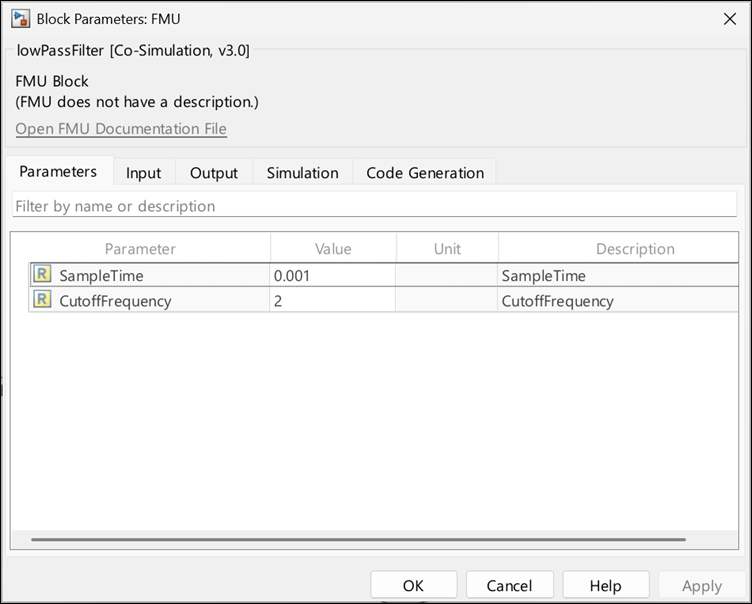
View and specify the parameters SampleTime and CutoffFrequency in the Parameters tab of the FMU Import block dialog box.
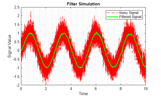
Simulate the model and observe the FMU output.
simOut = sim("FirstOrderLowPassFilterFMU.slx");

figure(1)
plot(simOut.yout{2}.Values,'--r','LineWidth',1);
hold on;
plot(simOut.yout{1}.Values,'g','LineWidth',2);
grid minor
xlabel('Time')
ylabel('Signal Value')
title('Filter Simulation')
legend('Noisy Signal', 'Filtered Signal')