2-Way Directional Valve (TL)
2-way directional valve in a thermal liquid network

Libraries:
Simscape /
Fluids /
Thermal Liquid /
Valves & Orifices /
Directional Control Valves
Description
The 2-Way Directional Valve (TL) block represents a two-way valve, such as a shut-off valve. Use this block to simulate a flow-reducing control element that responds to pressures in another part of the system.
The block uses a variable orifice to control the flow between ports A and B. The physical signal at port S triggers the spool motion to open or shut the valve. For more details about how the block calculates flow rate through a variable orifice, see Orifice (TL).
Orifice Parameterizations
You can parameterize the valve opening linearly or by using tabulated data.
When you set Orifice parameterization to
Linear - Area vs. spool travel, the opening area
is a linear function of the spool travel distance.
where
Aorifice is the opening area.
ΔS is the spool travel distance input at port S.
ΔSmax is the value of the Spool travel between closed and open orifice parameter.
ALeak is the value of the Leakage area parameter.
Amax is the value of the Maximum orifice area parameter.
Note the linear scaling from ALeak to Amax in the figure.

When the valve is in a near-open or near-closed position in the linear parameterization, you can maintain numerical robustness in your simulation by adjusting the Smoothing factor parameter. If the Smoothing factor parameter is nonzero, the block smoothly saturates the opening area between Aleak and Amax. For more information, see Numerical Smoothing.
When you set Orifice parameterization to
Tabulated data - Area vs. spool travel, the block
uses the Spool travel vector and Orifice area
vector parameters to define the relationship between
Aorifice and
ΔS by interpolation.
Aleak and
Amax are the first and last
parameters of the Orifice area vector parameter, respectively.

When you set Orifice parameterization to
Tabulated data - Volumetric flow rate vs. spool travel and
                        pressure drop
, the block uses the Volumetric flow
rate table, q(ds,dp), Pressure drop vector,
dp, and Spool travel vector, ds parameters
to define the volumetric flow rate,
q(ΔS,p).

When you set Orifice parameterization to
Tabulated data - Mass flow rate vs. opening and pressure
                        drop
the block calculates the mass flow rate directly from the
spool position and the pressure drop across the valve. The relationship between
the three variables can be nonlinear and it is given by the tabulated data in
the Spool travel vector, ds, Pressure drop
vector, dp, and Mass flow rate table,
mdot(ds,dp) parameters.

Visualize Orifice Openings
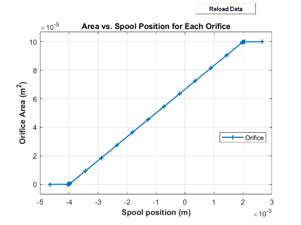
To generate a characteristic plot of the valve, click the Plot button next to Valve characteristics. The plot shows the valve open area or volumetric flow rate as a function of spool position.
To update the data after changing the block parameters, click Reload Data in the figure window.
This figure shows the valve configuration with:
Spool position at maximum orifice area set to
2e-3m.Spool travel between closed and open orifice set to
6e-3m.
All other parameters are at the default values.
Faults
To model a fault, in the Faults section, click the Add fault hyperlink next to the fault that you want to model. Use the fault parameters to specify the fault properties. For more information about fault modeling, see Introduction to Simscape Faults.
You can choose the type of fault by using the Spool position when faulted parameter:
Negative— The block freezes the valve at its smallest value. The table shows which value the block uses depending on the setting of the Orifice parameterization parameter.Orifice parameterization Parameter Setting Freeze Position Value Linear - Area vs. spool travelLeakage area parameter Tabulated data - Area vs. spool travelFirst element of the Orifice area vector parameter Tabulated data - Volumetric flow rate vs. spool travel and pressure dropFirst row of the Volumetric flow rate table, q(ds,dp) parameter Tabulated data - Mass flow rate vs. spool travel and pressure dropFirst row of the Mass flow rate table, mdot(ds,dp) parameter Positive— The valve freezes at its largest value. The table shows which value the block uses depending on the setting of the Orifice parameterization parameter.Orifice parameterization Parameter Setting Freeze Position Value Linear - Area vs. spool travelMaximum opening area parameter Tabulated data - Area vs. spool travelLast element of the Orifice area vector parameter Tabulated data - Volumetric flow rate vs. spool travel and pressure dropLast row of the Volumetric flow rate table, q(ds,dp) parameter Tabulated data - Mass flow rate vs. spool travel and pressure dropLast row of the Mass flow rate table, mdot(ds,dp) parameter Maintain last value— The valve freezes at its last value. The table shows which value the block uses depending on the setting of the Orifice parameterization parameter.Orifice parameterization Parameter Setting Freeze Position Value Linear - Area vs. spool travelThe valve open area when the trigger occurred Tabulated data - Area vs. spool travelThe valve open area when the trigger occurred Tabulated data - Volumetric flow rate vs. spool travel and pressure dropCurrent position Tabulated data - Mass flow rate vs. spool travel and pressure dropCurrent position When you set Orifice parameterization to
Tabulated data - Volumetric flow rate vs. spool travel and pressure droporTabulated data - Mass flow rate vs. spool travel and pressure drop, the volumetric flow rate or mass flow rate continues to change according to pressure changes in the valve after the valve freezes.
Due to numerical smoothing at the extremes of the valve area, in the linear parameterization, the minimum area that he block uses is larger than the Leakage area, and the maximum is smaller than the Maximum orifice area, in proportion to the Smoothing factor value. For more information, see Numerical Smoothing.
Examples

Aircraft Fuel Supply System with Three Tanks
Model an aircraft fuel supply system consisting of three tanks and an engine.