Use a Data Dictionary to Tune and Generate Structured Text Code for Multiple Plants
R2026bThis example shows how to use a Simulink® data dictionary (SLDD) and Simulink® PLC Coder™ to generate Structured Text for a temperature zone Proportional-Integral-Derivative (PID) controller model across different plants, where only the tuning values change from plant to plant. A data dictionary is a persistent repository of data that is relevant to your model.
Set Up the Data Dictionaries
The control logic and the I/O interface are identical for every plant. A shared dictionary Common.sldd holds the interface bus types, and the plant dictionaries PlantA.sldd, PlantB.sldd holds only that plant's PID loop gain values. Binding the model to a different plant dictionary and regenerating produces code with the same structure but different gain values.
Create the shared data dictionary Common.sldd and the per-plant dictionaries PlantA.sldd, PlantB.sldd, by using the setupThermalControlDictionaries helper function.
setupThermalControlDictionaries;
Created dictionaries Common.sldd, PlantA.sldd, PlantB.sldd
Open the Model
Open the ThermalZonePID model. The model contains the PID controller for a thermal zone in multiple plants. Each plant has its own data dictionary with the gain values for that plant. To generate code for the plant, you switch the model to use the data dictionary for that plant, which causes the generated code to contain the gain values for that plant.
Open the model and update the diagram.
mdl = "ThermalZonePID";
open_system(mdl)
set_param(mdl, SimulationCommand="update");
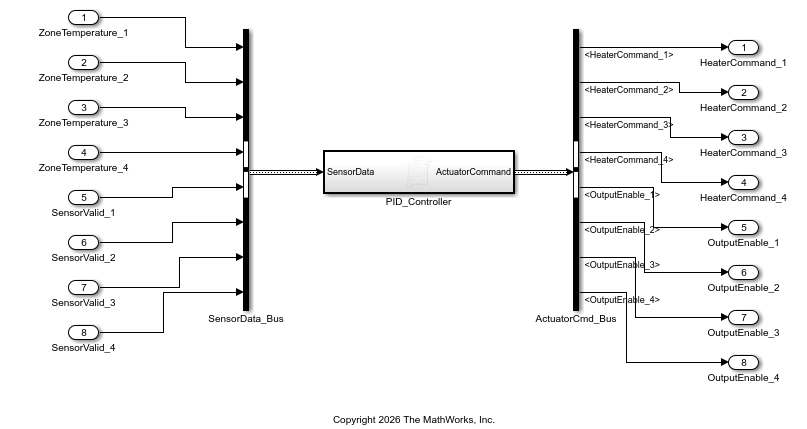
The model contains a single PID_Controller subsystem. The input to the subsystem is the SensorData bus which includes the per-zone temperature and temperature data valid signals. The subsystem outputs the ActuatorCommand bus which contains the per-zone heater command and enable signals. The Common.sldd data dictionary defines the SensorData and ActuatorCommand buses.
Configure Model and Generate Code
You can generate code for the ThermalZONePID model by using the PLC Coder app or by using the plcgeneratecode and plcopenconfigset functions.
Generate Code Using the PLC Coder App
To configure the model and generate Structured Text using the PLC Coder app:
Select the
PID_Controllersubsystem and, in the Apps tab, select PLC Coder.In the PLC Code tab, click Settings. In the Configuration Parameters dialog box, click PLC Code Generation Settings.
Change the Target IDE parameter to
Schneider Electric - EcoStruxure Control Expert. Click OK.Click Generate PLC Code. The generated Structured Text file appears in the
plcsrcfolder.To generate code for Plant B:
In the Modeling tab click Model Explorer.
In the Model Hierarchy pane, click External Data.
In the External Data pane, click Browse and select
PlantB.sldd. Click Apply.In the PLC Code tab, click Generate PLC Code.
Configure Model and Generate Code Programmatically
Set the target IDE to Schneider Electric - EcoStruxure Control Expert, bind the model to the Plant A dictionary, and then generate Structured Text code.
plcopenconfigset(mdl);
set_param(mdl, PLC_TargetIDE="schneider");
set_param(mdl, DataDictionary="PlantA.sldd");
Generate code for Plant A.
generatedFilesA = plcgeneratecode(mdl + "/PID_Controller");### Generating PLC code for 'ThermalZonePID/PID_Controller'. ### Using model settings from 'ThermalZonePID' for PLC code generation parameters. ### Begin code generation for IDE Schneider Electric - EcoStruxure Control Expert (schneider). ### Emit PLC code to file. ### Creating PLC code generation report index.html. ### PLC code generation successful for 'ThermalZonePID/PID_Controller'. ### Generated files: plcsrc/ThermalZonePID.xdb
plantAFile = string(generatedFilesA{1});
[plantADir,plantAName,plantAExt] = fileparts(plantAFile);
copyfile(plantAFile, fullfile(plantADir, plantAName + "_PlantA" + plantAExt));
Switch the data dictionary to Plant B and regenerate the Structured Text code. The model and subsystem are unchanged, only the dictionary binding changes which causes the PID gain values to change.
set_param(mdl, DataDictionary="PlantB.sldd"); generatedFilesB = plcgeneratecode(mdl + "/PID_Controller");
### Generating PLC code for 'ThermalZonePID/PID_Controller'.
### Using model settings from 'ThermalZonePID' for PLC code generation parameters.
### Begin code generation for IDE Schneider Electric - EcoStruxure Control Expert (schneider).
### Emit PLC code to file.
### Creating PLC code generation report index.html.
### PLC code generation successful for 'ThermalZonePID/PID_Controller'.
### Generated files:
plcsrc/ThermalZonePID.xdb
plantBFile = string(generatedFilesB{1});
copyfile(plantBFile, fullfile(plantADir, plantAName + "_PlantB" + plantAExt));
Examine the Generated Structured Text Code
To display the Zone 1 PID computation from each plant's generated code, use coder.example.extractLines. The code structure is identical, only the inlined gain values differ.
Plant A (, , ):
coder.example.extractLines(fullfile(plantADir, plantAName + "_PlantA" + plantAExt), "<S1>/Kd_1", "End of Saturate")
         *  Gain: '<S1>/Kd_1'
         *  Gain: '<S1>/Ki_1'
         *  Gain: '<S1>/Kp_1'
         *  Sum: '<S1>/Diff_1'
         *  Sum: '<S1>/Error_1'
         *  UnitDelay: '<S1>/Delay_1' *)
        rtb_Saturation_1 := ((((22.0 - SensorData_c.ZoneTemperature_1) - Delay_1_DSTATE) * 10.0) * 0.05) + (((22.0 - SensorData_c.ZoneTemperature_1) * 2.5) + (0.4 * Integrator_1_DSTATE));
        (* Saturate: '<S1>/Saturation_1' *)

        IF rtb_Saturation_1 > 100.0 THEN
            rtb_Saturation_1 := 100.0;
        ELSIF rtb_Saturation_1 < 0.0 THEN
            rtb_Saturation_1 := 0.0;
        END_IF;
Plant B (, , ):
coder.example.extractLines(fullfile(plantADir, plantAName + "_PlantB" + plantAExt), "<S1>/Kd_1", "End of Saturate")
         *  Gain: '<S1>/Kd_1'
         *  Gain: '<S1>/Ki_1'
         *  Gain: '<S1>/Kp_1'
         *  Sum: '<S1>/Diff_1'
         *  Sum: '<S1>/Error_1'
         *  UnitDelay: '<S1>/Delay_1' *)
        rtb_Saturation_1 := ((((22.0 - SensorData_c.ZoneTemperature_1) - Delay_1_DSTATE) * 10.0) * 0.02) + (((22.0 - SensorData_c.ZoneTemperature_1) * 3.1) + (0.55 * Integrator_1_DSTATE));
        (* Saturate: '<S1>/Saturation_1' *)

        IF rtb_Saturation_1 > 100.0 THEN
            rtb_Saturation_1 := 100.0;
        ELSIF rtb_Saturation_1 < 0.0 THEN
            rtb_Saturation_1 := 0.0;
        END_IF;
The generated code uses the PID values for plant B. The FUNCTION_BLOCK structure and STRUCT type definitions are identical between the two files; only the PID gain constants changed, demonstrating that switching data dictionaries is all that you need to re-tune the controller for a different plant.

