Read Temperature from an NXP FXOS8700CQ Sensor Available on NXP FRDM-K64F Hardware
This example shows you how to use Simulink® Coder™ Support Package for NXP™ FRDM-K64F Board to configure and read temperature from an NXP FXOS8700CQ sensor, which is a I2C-based sensor.
Introduction
Simulink Coder Support Package for NXP FRDM-K64F Board enables you to use the I2C Controller Read/ I2C Controller Write blocks to communicate with I2C-based devices.
In this example, you learn how to communicate to the NXP FXOS8700CQ sensor, which is available on the NXP FRDM-K64F board. FXOS8700CQ is a small, low-power, 3-axis, linear accelerometer and 3-axis, magnetometer combined into a single package. This sensor is interfaced with the NXP FRDM-K64F board using the I2C bus.
For more details about the device, refer to the FXOS8700CQ datasheet.
This examples shows you how to use the I2C Controller Read and I2C Controller Write blocks to read the temperature values from the FXOS8700CQ sensor. To read Accelerometer data or Magnetometer data from the sensor, use the FXOS8700 6-Axes Sensor block available in the NXP FRDM-K64F block library.
Prerequisites
Study these examples:
Required Hardware
To run this example, you need this hardware:
NXP FRDM-K64F Board
USB type A to Micro-B cable
Open Model
Open example model freedomk64f_I2C_tempSensor.
Task 1 - Configure the Model for NXP FRDM-K64F Hardware
Configure the model for the NXP FRDM-K64F hardware.
1. Open the model Configuration Parameters dialog box. In the model window toolstrip, click Simulation > Model Configuration Parameters.
2. Set model configuration parameter Hardware board to NXP FRDM-K64F.
3. Click OK.
Task 2 - Configure the Model to Read Temperature
Initialize configuration registers of the NXP FXOS8700CQ sensor to read the temperature data.
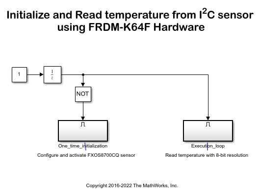
1. Note the two subsystems in the model.
The
One_time_initializationsubsystem configures the NXP FXOS8700CQ sensor.
The
Execution_loopsubsystem reads the 8-bit temperature.
The
One_time_initializationsubsystem executes once at the first step of the execution of the model. For the rest of the execution time, theExecution_loopsubsystem runs. This selective execution of subsystems is handled by using the Unit Delay and the Enabled Subsystem blocks.
The One_time_initialization subsystem performs two functions. It sets the mode of the sensor and activates the sensor.
2. Configure the I2C Controller Write block to set the mode of the NXP FXOS8700CQ sensor. According to the FXOS8700CQ datasheet, the TEMP register of the FXOS8700CQ sensor gives a valid temperature reading when the sensor is set to magnetometer mode or hybrid mode. You can set the mode of the sensor by writing to the 'm_hms' bits of the M_CTRL_REG1 register.
Open the
One_time_initializationsubsystem.

Open the I2C Controller Write1 block.
The onboard FXOS8700CQ sensor is connected to the I2C Module of the processor through the pins PTE24 (SCL) and PTE25 (SDA). As documented in the FRDM K64F reference manual these pins belong to I2C module 0. Set the I2C module parameter to 0.
The Peripheral address parameter is set to '0x1D' and parameter Peripheral register address is set to '0x5B'. The FXOS8700CQ datasheet identifies
0x1Das the peripheral address of the device and0x5Bis the address of register M_CTRL_REG1.
Set the Peripheral byte order parameter to
Big Endian. The Configuration Register has a size of 8 bits and its value needs to be sent over the I2C bus using Big Endian.
5. Configure the I2C Controller Write block to activate the NXP FXOS8700CQ sensor.
In the
One_time_initialization subsystem, open the I2C Controller Write2 block.
As explained in step 4, the I2C module and the Peripheral address parameters are set to
0and0x1D, respectively.
The Peripheral register address parameter is set to
0x2A, which aligns with the register address documented in the FXOS8700CQ datasheet. for register CTRL_REG1.
The sensor is in standby mode after reset. You can set the sensor to Active mode by setting the active bit in the CTRL_REG1 to 1 as documented in the FXOS8700CQ datasheet.
6. In the One_time_initialization subsystem, note the following:
The Constant1 and Constant2 blocks hold the value of '0x01' to be written to the M_CTRL_REG1 and CTRL_REG1 registers. The sensor is set to magnetometer only mode by writing
0b01to them_hmsbits of the M_CTRL_REG1 register.
The I2C Controller Read1 and I2C Controller Read2 blocks, which are connected to the Display blocks, help to verify that the correct data is written to the configuration registers. The I2C Controller Read block uses the same settings as the respective I2C Controller Write block.
The priority of the I2C Controller Write1 block is set to be higher than the priority of the I2C Controller Write2 block. This sets the mode of the sensor before the sensor is activated. The priority of the I2C Controller Write block is set to be higher than the priority of the respective I2C Controller Read block so that the value of the Configuration Register is read after it is set. To set the priority of a block, right-click the block and set the value of Properties > General > Priority. For more information about block priorities and their impact on block execution order, see Specify Block Properties.
7. Open and observe the following in the Execution_loop subsystem.

Open the I2C Controller Read block. As mentioned for the I2C Controller Write block, notice that the I2C Module property is set to
0and Peripheral address is set to0x1D.
The FXOS8700CQ datasheet lists 0x51 as the address of the TEMP register, which contains the temperature value in 8-bit 2's complement form. To align with that specification, the Peripheral register address property is set to
0x51, Data type is set toint8, and Data size (N) is set to1.
The sensitivity of the sensor is 0.96 C/LSB. Therefore, the Gain block performs a multiplication by 0.96 to give the temperature value in degree Celsius (C).
Task 3 - Run the Model in External Mode
Run the model in external mode to monitor the temperature. For more information on external mode, see Code Verification and Validation with External Mode.
1. In the model window toolstrip, set Simulation mode to External.
2. In the toolstrip, click Run. The model runs in external mode.
3. Open the One_time_initialization subsystem.
4. Verify that the Display blocks show a value of 0x01 in hexadecimal, corresponding to the desired configuration register value.
5. In the Execution_loop subsystem, monitor the Display block to observe the FXOS8700CQ temperature reading in degree Celsius. The onboard LED glows when the Display block in the model shows a temperature above 27 degree Celsius.
6. Change the threshold value in the Switch block according to your ambient temperature and click Apply. See the onboard LED glow when the temperature exceeds the new threshold value.
7. To end the external mode execution, click Stop.
Other Things to Try
Follow the steps in this example to communicate to other I2C based sensors.