QZSS Receiver Positioning Using L1C/A or L1C/B Signals
R2026bThis example shows how to estimate the position of a stationary receiver using a multi-satellite Quasi-Zenith Satellite System (QZSS) signal. The example reads navigation data from a QZSS Receiver Independent Exchange (RINEX) file, creates a satellite scenario and generates the L1C/A or L1C/B signals for visible satellites. It then propagates the composite waveform through Doppler, delay, and noise, and processes the received signal through acquisition, tracking, synchronization, decoding, and position estimation.
QZSS, also known as Michibiki, is a regional satellite navigation system operated by the cabinet office of the government of Japan. It provides satellite positioning, navigation, and timing (PNT) services that complement Global Positioning System (GPS) in the Asia-Oceania region. The QZSS constellation consists of satellites in quasi-zenith orbits (QZO) and geostationary orbits (GEO). The quasi-zenith orbit design produces an asymmetrical figure-eight ground track, ensuring that at least one satellite is always near the zenith over Japan, providing high-elevation-angle signals optimized for urban canyons and mountainous terrain.
Example Workflow
The simulation consists of two parts. The transmitter generates signals from multiple QZSS satellites. The receiver processes the signals to recover navigation data and estimate the receiver position.
Transmitter chain
Load orbital parameters from a RINEX file and create a
satelliteScenariowith the visible QZSS satellites.Compute the Doppler shift and propagation delay between each satellite and the receiver at every simulation time step.
Create a navigation data configuration object containing ephemeris and clock parameters extracted from the RINEX file.
Encode the navigation message into data bits as specified by the QZSS standard [1].
Generate the QZSS L1C/A or L1C/B waveform and pass the signal through a propagation channel that applies the Doppler shift, signal delay, and additive noise.
Receiver Chain
Acquire visible satellites using
gnssSignalAcquirer, which estimates the coarse Doppler offset and code phase for each detected satellite.Track the signal using
gnssSignalTrackerobject.Detect the frame boundary by using the
gnssFrameSynchronizerto identify the synchronization pattern transmitted with each subframe.Decode the navigation data from the detected subframes.
Compute pseudoranges from the estimated signal transit times, determine position of each satellite from the decoded ephemeris, and estimate the receiver position.
Initialize Simulation Parameters
Define the parameters for the simulation. Specify ShowVisualizations as true to display plots in simulation. You can enable WriteWaveformToFile to save the generated baseband waveform to a file, which you can replay later with another receiver. Select the WaveformType as L1C/A or L1C/B.
ShowVisualizations =false; WriteWaveformToFile =
false; WaveformType =
"L1C/A"; % Waveforms supported L1C/A and L1C/B
Set the simulationDuration long enough for the receiver to acquire satellites, synchronize to the navigation frame, and compute a position fix. Use a minimum duration of 55 seconds because the receiver must collect enough ephemeris data from the LNAV subframes for successful position estimation.
simulationDuration = 2; % In seconds

% Define sample rate (Hz) of the generated waveform
fs = 8e6;

% Define the receiver position in [latitude(deg) longitude(deg) altitude(m)]
rxpos = [30.556498 131.015424 86.164818];
A QZSS signal takes about 130 milliseconds to reach the ground from the satellite. Set rxWaitTime to at least this value so that the receiver starts acquisition after the first meaningful samples arrive. Otherwise, the receiver processes only noise.
rxWaitTime = 150e-3; % In secondsInitialize the physical constants and link budget parameters used to compute received signal power and thermal noise.
c = physconst("LightSpeed");
Dt = 12;                      % Transmit antenna directivity (dBi)
DtLin = db2pow(Dt);
Dr = 4;                       % Receive antenna directivity (dBi)
DrLin = db2pow(Dr);
Pt = 150;                      % Typical transmission power of satellite (watts)
k = physconst("boltzmann");
T = 300;                      % System noise temperature (K)
Nr = k*T*fs;                  % Noise power across the sampling bandwidth
Initialize Signal Parameters
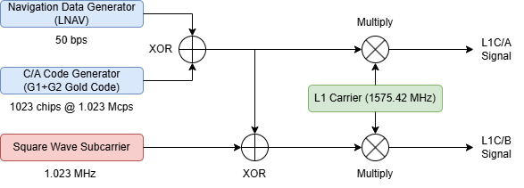
The QZSS L1C/A signal is transmitted on the L1 carrier at 1575.42 MHz. It uses binary phase shift keying (BPSK) modulation and a Gold code with 1023 chips at a chipping rate of 1.023 Mchip/s. As a result, the code period is 1 milliseconds. The navigation data rate is 50 bps. This signal structure is interoperable with the GPS L1 C/A signal, so QZSS receivers can reuse GPS L1 C/A processing algorithms.
The QZSS L1C/B signal uses the same C/A code with binary offset carrier modulation, BOC(1,1). This modulation multiplies the code by a 1.023 MHz square-wave subcarrier. As a result, the spectral energy shifts away from the center frequency, and the autocorrelation function splits into a sharp main peak and two secondary peaks. Sharper main peak improves code-tracking precision and multipath rejection. However, the secondary peaks introduce correlation ambiguity that the acquisition and tracking stages must handle. This diagram illustrates the waveform generation of both the signal types.
fc = 1575.42e6;                                       % Carrier frequency (Hz)
codeLen = 1023;                                       % Length of the spreading code (chips)
bitRate = 50;                                         % Navigation data bit rate (bits/s)
chipRate = 1.023e6;                                   % Spreading code chip rate (chips/s)
oneCodeDuration = codeLen/chipRate;
oneBitDuration = 1/bitRate;
numCodeBlocksPerBit = oneBitDuration/oneCodeDuration;
samplesPerCodeBlock = oneCodeDuration*fs;
subframeDuration = 6;                                 % In seconds
The example processes the data in 1 ms chunks, which correspond to one code block. At each step, the example generates one code block from all visible satellites, propagates it through the channel, and processes it at the receiver.
stepTime = oneCodeDuration;
numStepsPerSubframe = subframeDuration/stepTime;
Configure Simulation
Read QZSS RINEX data, generate navigation data, and configure the satellite scenario. Then compute access, Doppler, and delay, and set up the waveform and tracker objects and receiver state variables.
Read RINEX Data for Navigation Data Configuration
Read a RINEX navigation file that contains orbital parameters for QZSS satellites. The broadcast ephemeris describes each satellite orbit using Keplerian parameters. NASA (National Aeronautics and Space Administration) Earthdata provides QZSS RINEX navigation data [2]. This example uses the data to create navigation configuration objects that generate QZSS legacy navigation (LNAV) message bits. Poor satellite geometry at certain times at the receiver location increases the dilution of precision (DOP) and can produce larger position errors.
rinexFileName = "BRDC00IGS_R_20261480000_01D_MN.rnx"; rinexData = rinexread(rinexFileName); timeStamps = string(unique(rinexData.QZSS.Time)); % Select from unique available datetime to simulate the example at different times tSel =timeStamps(3); qzssAtTime = rinexData.QZSS(datetime(tSel),:); % Extract unique QZSS satellites from the RINEX data. [~,satIdx] = unique(qzssAtTime.SatelliteID); qzssData = qzssAtTime(satIdx,:); % Create navigation configuration objects from the RINEX data for generating the QZSS-compatible LNAV navigation message navcfg = HelperQZSSRINEX2Config(qzssData);
Generate Navigation Data
Encode the full LNAV message for each satellite using the ephemeris parameters from the RINEX file. Each message contains 37,500 bits, which correspond to 25 frames, 5 subframes per frame, and 300 bits per subframe. As a result, a complete LNAV message takes 12.5 minutes to transmit. Align the time-of-week (TOW) counters across all satellites so that the message starts with subframe 1. Increment the handover word TOW (HOWTOW) counter by 1 for each 6-second subframe.
% Extract the navigation parameters for the available unique QZSS satellites.
[mintow,locmintow] = min([navcfg(:).HOWTOW]);
mintow = ceil((mintow-1)/5)*5 + 1;
[navcfg(:).HOWTOW] = deal(mintow);
firstsubframeID = mod(mintow-1,125) + 1;
frameID = ceil(firstsubframeID/5);
allFrameIDs = [frameID:25,1:(frameID-1)];
[navcfg(:).FrameIndices] = deal(allFrameIDs);

numNavBits = 37500;
navdata = zeros(numNavBits,length(navcfg));
eph = cell(1,length(navcfg));
reqCEIFields = ["PRNID", "WeekNumber", "ReferenceTimeOfEphemeris", "SemiMajorAxisLength", ...
    "MeanMotionDifference", "MeanAnomaly", "Eccentricity", ...
    "ArgumentOfPerigee", "Inclination", "InclinationRate", ...
    "HarmonicCorrectionTerms", "RateOfRightAscension", ...
    "LongitudeOfAscendingNode"];
for isat = 1:length(navcfg)
    % Set the clock bias and group delay differential to zero because this example does not model satellite clock errors in the transmitted signal.
    navcfg(isat).SVClockCorrectionCoefficients = [0 0 0];
    navcfg(isat).GroupDelayDifferential = 0;
    navdata(:,isat) = HelperGPSNAVDataEncode(navcfg(isat));
    for i = 1:numel(reqCEIFields)
        eph{isat}.(reqCEIFields(i)) = navcfg(isat).(reqCEIFields(i));
    end
end
Setup Satellite Scenario
Create a satellite scenario with start and stop times from the RINEX ephemeris. Add QZSS satellites to the scenario using their orbital parameters. The current QZSS constellation includes satellites in QZO and GEO, with PRN IDs from 193 to 202 [1]. Although the standard assigns PRN IDs 203 to 206 to the L1C/B signal, this example uses the PRN IDs available in the RINEX data for the simulation.The scenario computes satellite positions over time using Keplerian orbital mechanics.
sc = satelliteScenario;
sc.SampleTime = stepTime;
sc.StartTime = HelperGNSSConvertTime(navcfg(locmintow).WeekNumber,...
    (mintow-1)*subframeDuration);
sc.StopTime = sc.StartTime + seconds(simulationDuration);
[sc,sat] = HelperAddQZSSSatellite(sc,eph);
Set up the receiver as a ground station with a minimum elevation constraint of 20 degrees. Exclude satellites below this elevation angle.
rx = groundStation(sc,rxpos(1),rxpos(2),Altitude=rxpos(3),MaskElevationAngle=20);
Compute Access, Doppler, and Propagation Delay
Determine which satellites are visible to the receiver. Then compute the time-varying Doppler shift and propagation delay for each visible satellite.
ac = access(sat,rx);
acstats = accessStatus(ac);

% Consider only the access status at the first time step since access does
% not change during the short simulation duration.
satindices = find(acstats(:,1));
numsat = length(satindices);

% Calculate Doppler shift over time for all the visible satellites
fShift = dopplershift(sat(satindices),rx,Frequency=fc);

% Calculate propagation delay over time for all the visible satellites
delays = latency(sat(satindices),rx);

% Compute the received power and SNR for each satellite using the free-space
% path loss equation.
Pr = (Pt*DtLin*DrLin)*(1./(4*pi*(fc+fShift).*delays).^2);
SNRs = 10*log10(Pr/Nr);                                    % (In dB)

PRNIDs = [navcfg(:).PRNID];
disp("Available satellites - " + num2str(PRNIDs(satindices)+192)) % Add 192 to convert the RINEX PRN index to the QZSS PRN identifier
Available satellites - 194 195 196 199 200
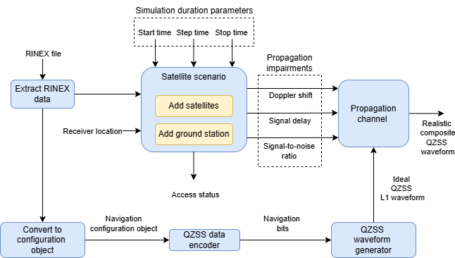
The following diagram summarizes the transmitter setup in this example.
Initialize Waveform and Tracker Objects
Set up the waveform generator, signal acquisition stage, tracking loop parameters, and propagation channel model. The waveform generator creates QZSS L1C/A or L1C/B baseband signals for all visible satellites. The propagation channel adds Doppler shift, signal delay, and additive white Gaussian noise (AWGN) to model realistic received signal conditions.
Use a phase-locked loop (PLL) to track carrier phase for data demodulation. Use a frequency-locked loop (FLL) to track carrier frequency for Doppler compensation. Use a delay-locked loop (DLL) to track code delay for pseudorange measurement. For L1C/B, the DLL uses a double-delta correlator instead of the standard early-minus-late discriminator used for L1C/A. This discriminator produces an S-curve with a single zero crossing at the true code phase, which resolves the BOC correlation ambiguity.
% Initialize the QZSS waveform generator for all visible satellites.
qzsswavegen = HelperQZSSWaveformGenerator(SignalType=WaveformType,PRNID=PRNIDs(satindices)+192,SampleRate=fs);

% Initialize the propagation channel object. The channel introduces
% frequency offset (Doppler), signal delay (propagation time), and AWGN to model realistic received signal conditions.
gnssChannel = HelperGNSSChannel(SampleRate=fs,RandomStream="mt19937ar with seed",Seed=73);

if strcmp(WaveformType,"L1C/A")
    [sigAcqType,sigTrkType] = deal("QZSS C/A");
elseif strcmp(WaveformType,"L1C/B")
    [sigAcqType,sigTrkType] = deal("QZSS C/B");
end

% Configure the acquisition module.
fRange = [-5e3 5e3];
fResolution = 50;
sigAcquisition = HelperGNSSSignalAcquirer(GNSSSignalType=sigAcqType,SampleRate=fs,FrequencyRange=fRange,FrequencyResolution=fResolution);

% Define the tracking loop noise bandwidths. These parameters control the
% trade-off between tracking accuracy (narrow bandwidth) and dynamic
% response (wide bandwidth).
PLLNoiseBW = 30;            % In Hz
FLLNoiseBW = 4;             % In Hz
DLLNoiseBW = 1;             % In Hz

sigTracker = HelperGNSSSignalTracker( ...
    GNSSSignalType=sigTrkType, ...
    SampleRate=fs, ...
    PLLNoiseBandwidth=PLLNoiseBW, ...
    FLLNoiseBandwidth=FLLNoiseBW, ...
    DLLNoiseBandwidth=DLLNoiseBW);
Optionally, initialize a baseband file writer to save the generated waveform for offline replay or use with an external receiver.
if WriteWaveformToFile ~= 0
    bbWriter = comm.BasebandFileWriter("qzssBBWaveform.bb",fs,0);
end
Initialize Receiver State Variables
Set up the storage arrays and parameters for the receiver processing state machine.
numSteps = ceil(simulationDuration/stepTime) + 1;
rxWaitTimeInSteps = ceil(rxWaitTime/stepTime);

maxNumTrackingChannels = 8;

% Properties required for storing outputs from tracking module
trackedWave = zeros(numSteps,maxNumTrackingChannels);
trackInfo = repmat(struct("PhaseError",0,"PhaseEstimate",0,...
    "FrequencyError",0,"FrequencyEstimate",0,...
    "DelayError",0,"DelayEstimate",0),numSteps,1);

% Bit synchronization parameters
numBitsForBitSync = 100;
numWaitingStepsForBitSync = numCodeBlocksPerBit*numBitsForBitSync;
minTimeForPosEst = 48.5;                                             % In seconds
minStepsForPosEst = minTimeForPosEst/stepTime;

% Bit and frame synchronization state
isBitSyncComplete = zeros(maxNumTrackingChannels,1);
[maxTransitionLocation,sampleCounter] = deal(zeros(maxNumTrackingChannels,1));
syncidx = zeros(maxNumTrackingChannels,1);

% Data decoder output
deccfg = cell(maxNumTrackingChannels,1);

% Initialize the receiver chain step count and first state, which is
% acquisition of the satellites
rxistep = 1;
isSynchronized = false;
nxtState = "acquisition";
Transmit-Receive Loop
Process the received signal through the complete receiver chain. At each step, generate one code block from all visible satellites. Then apply propagation channel effects, including Doppler shift, signal delay, and noise. Next, process the composite received signal with the receiver state machine.
The receiver state machine progresses through the following stages:
State | Action |
Acquisition | Correlate the received signal with local C/A-code replicas across a Doppler/code-phase search grid to detect satellites and estimate coarse parameters |
Tracking | Refine carrier phase, frequency, and code delay using phase-locked loop (PLL), frequency-locked loop (FLL) and delay-locked loop (DLL) respectively. The tracking loops produce integrated prompt correlator outputs that carry the navigation data |
Bit synchronization | Identify the 20-ms data bit boundaries by detecting transitions in the integrated tracking output |
Frame synchronization | Detect the Telemetry (TLM) preamble pattern to locate subframe boundaries |
Data decoding | Extract ephemeris, clock corrections, and TOW from decoded subframes |
Position estimation | Compute pseudoranges from measured code delays and estimate receiver coordinates using least-squares |
Three-dimensional position estimation requires at least four satellites with successfully decoded ephemeris.
tic
for istep = 1:numSteps
    % Generate waveform for the current 1 ms code block
    bitidx = floor((istep - 1)/numCodeBlocksPerBit) + 1;
    CodeBlockNumber = mod(istep - 1,numCodeBlocksPerBit);
    if CodeBlockNumber == 0
        OnebitWaveform = qzsswavegen(navdata(bitidx,satindices));
    end
    iqsig = OnebitWaveform(CodeBlockNumber*samplesPerCodeBlock + (1:samplesPerCodeBlock),:);

    % Introduce propagation channel effects to the transmitted signal
    gnssChannel.FrequencyOffset = fShift(:,istep).';
    gnssChannel.SignalDelay = delays(:,istep).';
    gnssChannel.SignalToNoiseRatio = SNRs(:,istep).';
    waveform = gnssChannel(iqsig);

    % Optionally write the waveform to a file
    if WriteWaveformToFile ~= 0
        bbWriter(waveform);
    end

    if strcmp(nxtState,"exit")
        break;
    end

    % Receiver
    if istep > rxWaitTimeInSteps
        while true
            switch(nxtState)
                case "acquisition"
                    % Initial synchronization
                    [acqd,corrval] = sigAcquisition(waveform,193:202);
                    PRNIDsToSearch = acqd(acqd(:,4).IsDetected==1,1).PRNID.';
                    doppleroffsets = acqd(acqd(:,4).IsDetected==1,2).FrequencyOffset;
                    codephoffsets = acqd(acqd(:,4).IsDetected==1,3).CodePhaseOffset;

                    numdetectsat = length(PRNIDsToSearch);
                    isFullDataDecoded = false(numdetectsat,1);
                    if numdetectsat > maxNumTrackingChannels
                        numdetectsat = maxNumTrackingChannels;
                    end

                    disp("The detected satellite PRN IDs: " + num2str(PRNIDsToSearch))

                    if numdetectsat > 3
                        % If four or more satellites are detected
                        framesyncbuffer = cell(1,numdetectsat);
                        framesync = cell(numdetectsat,1);
                        prev_cntr = ones(numdetectsat,1);
                        sigTracker.PRNID = PRNIDsToSearch(1:numdetectsat);
                        sigTracker.InitialFrequencyOffset = doppleroffsets(1:numdetectsat);
                        sigTracker.InitialCodePhaseOffset = codephoffsets(1:numdetectsat);
                        for isat = 1:numdetectsat
                            framesync{isat} = gnssFrameSynchronizer("SignalType","GPS-LNAV");
                        end
                        nxtState = "tracking";

                        if ShowVisualizations ~= 0
                            % Correlation plot for first detected satellite
                            figure
                            mesh(fRange(1):fResolution:fRange(2),0:size(corrval,1)-1,corrval(:,:,1))
                            xlabel("Doppler Offset")
                            ylabel("Code Phase Offset")
                            zlabel("Correlation")
                            title("Correlation Plot for PRN ID: " + PRNIDsToSearch(1));
                        end
                    else
                        % If acquisition fails, that is, less than four
                        % satellites are detected, the receiver chain
                        % exits.
                        nxtState = "exit";
                        break
                    end

                case "tracking"
                    [trackedWave(rxistep,1:numdetectsat),trackInfo(rxistep)] = sigTracker(waveform);
                    nxtState = "buffer";

                case "buffer"
                    % Accumulate samples for bit-synchronized satellites
                    for isat = 1:numdetectsat
                        if isBitSyncComplete(isat)
                            sampleCounter(isat) = sampleCounter(isat) + 1;
                            framesyncbuffer{isat}(sampleCounter(isat)) = trackedWave(rxistep,isat);
                        end
                    end

                    % Check if enough samples are collected
                    if ~isSynchronized && rxistep > numWaitingStepsForBitSync
                        nxtState = "bit-synchronization";
                    elseif isSynchronized && any(mod(sampleCounter(1:numdetectsat),numStepsPerSubframe) == 0 & sampleCounter(1:numdetectsat) > 0)
                        nxtState = "data-decode";
                    else
                        nxtState = "tracking";
                        break;
                    end

                case "bit-synchronization"
                    for isat = 1:numdetectsat
                        if ~isBitSyncComplete(isat)
                            maxTransitionLocation(isat) = ...
                                gnssBitSynchronize( ...
                                imag(trackedWave(1:numWaitingStepsForBitSync,isat)),...
                                numCodeBlocksPerBit);
                            isBitSyncComplete(isat) = 1;
                            sampleCounter(isat) = rxistep - maxTransitionLocation(isat) + 1;
                            framesyncbuffer{isat} = trackedWave( ...
                                maxTransitionLocation(isat):rxistep,isat);
                        end
                    end
                    if all(isBitSyncComplete(1:numdetectsat))
                        isSynchronized = true;
                    end
                    nxtState = "tracking";
                    break;

                case "data-decode"
                    for isat = 1:numdetectsat
                        if mod(sampleCounter(isat),numStepsPerSubframe) == 0 && sampleCounter(isat) > 0
                            samples = framesyncbuffer{isat}(sampleCounter(isat) - ...
                                numStepsPerSubframe+1:sampleCounter(isat));
                            sym = mean(reshape(samples,numCodeBlocksPerBit,[]));
                            bits = imag(sym) < 0;
                            rxsubframes = framesync{isat}(bits(:));
                            if ~isempty(rxsubframes)
                                s = info(framesync{isat});
                                syncidx(isat) = s.SyncIndex;
                                deccfg{isat}.PRNID = PRNIDsToSearch(isat);
                                deccfg{isat} = HelperGPSLNAVDataDecode(rxsubframes,deccfg{isat});
                                prev_cntr(isat) = rxistep;
                            end
                            isFullDataDecoded(isat) = isfield(deccfg{isat},"PRNID") && ...
                                all(isfield(deccfg{isat},reqCEIFields));
                        end
                    end

                    % Check if enough data for position estimation
                    % if rxistep > minStepsForPosEst && nnz(syncidx(1:numdetectsat)) >= 4
                    if nnz(isFullDataDecoded) >= 4 && rxistep >= minStepsForPosEst
                        nxtState = "pos-estimate";
                    else
                        nxtState = "tracking";
                        break;
                    end

                case "pos-estimate"
                    codeOffsetTime = codephoffsets(1:numdetectsat)/chipRate;
                    trackingOffsetTime = [trackInfo(rxistep).DelayEstimate]/chipRate;
                    bitsyncTime = (maxTransitionLocation(1:numdetectsat)-1)*oneCodeDuration;
                    framesyncTime = (syncidx(1:numdetectsat)-1)*numCodeBlocksPerBit*oneCodeDuration;

                    % Calculate transmission delay from these parameters
                    delayEst = codeOffsetTime(:) - trackingOffsetTime(:) + bitsyncTime + framesyncTime;
                    validDelay = delayEst(syncidx(1:numdetectsat) ~= 0);
                    rho = validDelay*c;

                    % Include TOW decoded from the received navigation message
                    tow = zeros(numdetectsat,1);
                    for isat = 1:numdetectsat
                        if isfield(deccfg{isat},"HOWTOW")
                            tow(isat) = deccfg{isat}.HOWTOW*6; % Each subframe has a duration of 6 seconds
                        end
                    end
                    tow = tow(syncidx(1:numdetectsat) ~= 0);
                    deccfg1 = deccfg(syncidx(1:numdetectsat) ~= 0);

                    [GPSWeek,timeofweek,deltaT] = deal(zeros(length(tow),1));
                    for isat = 1:length(tow)
                        if isFullDataDecoded(isat)
                            GPSWeek(isat) = deccfg1{isat}.WeekNumber;
                            timeofweek(isat) = tow(isat);
                        end

                        % Satellite clock bias correction on pseudo-range
                        clk = [0 0 0];
                        if isfield(deccfg1{isat},"SVClockCorrectionCoefficients")
                            clk = deccfg1{isat}.SVClockCorrectionCoefficients;
                        end
                        dt = timeofweek(isat) - deccfg1{isat}.ReferenceTimeOfEphemeris;
                        deltaT(isat) = clk(1) + clk(2)*dt + clk(3)*(dt^2);

                        TGD = 0;
                        if isfield(deccfg1{isat},"GroupDelayDifferential")
                            TGD = deccfg1{isat}.GroupDelayDifferential;
                        end
                        rho(isat) = rho(isat) + (deltaT(isat) + TGD)*c;
                    end

                    if nnz(isFullDataDecoded) >= 4
                        [satpos,~] = HelperGNSSSatelliteStates(deccfg1(isFullDataDecoded),max(GPSWeek),max(timeofweek)+6); % Add 6 seconds to TOW because the frame synchronizer returns the previous subframe after synchronization.
                        [rxposest,~,hdop,vdop] = receiverposition(rho(isFullDataDecoded),satpos);
                        estRxPosNED = lla2ned(rxposest,rxpos,"ellipsoid");
                        distanceError = vecnorm(estRxPosNED);
                        fprintf("Estimated receiver position is [%.4f°, %.4f°, %.0f m] with an estimated error of %.2f m.\n", rxposest(1),rxposest(2),rxposest(3),distanceError);
                        if hdop > 20
                            warning("Dilution of Precision (DOP) ratings are poor. The position " + ...
                                "estimation error can be high.")
                        end
                    end

                    nxtState = "exit";
                    break;
            end
        end
        rxistep = rxistep + 1;
    end
    if ~mod(istep,1/stepTime)
        disp("Processed " + (istep*stepTime) + " sec of data at the receiver.")
    end
end
The detected satellite PRN IDs: 199 200 194 196 195
Processed 1 sec of data at the receiver.
Processed 2 sec of data at the receiver.
toc
Elapsed time is 31.085771 seconds.
If simulationDuration is too short for a full data decode, load reference data for the default example configuration to demonstrate the final positioning step.
if rxistep <= minStepsForPosEst
    % The parameters that are loaded here are valid for the default
    % configuration of this example
    load QZSSReceiverPositionProperties;

    % When loading the parameters for default configuration, update the
    % isFullDataDecoded variable with all ones to compute the receiver
    % position.
    isFullDataDecoded = true(length(rho),1);

    defaultRINEXFileName = "BRDC00IGS_R_20261480000_01D_MN.rnx";
    defaultRxPos = [30.556498 131.015424 86.164818];

    if ~(strcmp(rinexFileName,defaultRINEXFileName) && isequal(rxpos,defaultRxPos))
        warning("Estimated receiver position may be different from what you provided" + ...
            " as the simulation didn't run for entire data." + ...
            " To get accurate receiver position, run the example" + ...
            " for at least 55 seconds of navigation data.");
    end

    [rxposest,~,hdop,vdop] = receiverposition(rho,satpos);
    estRxPosNED = lla2ned(rxposest,rxpos,"ellipsoid");
    distanceError = vecnorm(estRxPosNED);
    fprintf("Estimated receiver position is [%.4f°, %.4f°, %.0f m] with an estimated error of %.2f m.\n", rxposest(1),rxposest(2),rxposest(3),distanceError);
end
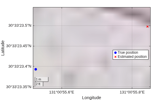
Estimated receiver position is [30.5565°, 131.0155°, 86 m] with an estimated error of 9.07 m.
If you enable visualizations, display the most recent tracked samples at the output of the tracking stage.
rxistep = rxistep - 1;
if ShowVisualizations ~= 0
    rxconstellation = comm.ConstellationDiagram(1,ShowReferenceConstellation=false, ...
        Title="Constellation diagram of signal at the output of tracking");
    rxconstellation(trackedWave(max(1,rxistep - 999):rxistep,1)/...
        rms(trackedWave(max(1,rxistep - 999):rxistep,1)))
end
If you enable waveform logging, release the baseband file writer after the simulation completes.
if WriteWaveformToFile ~= 0
    release(bbWriter)
end
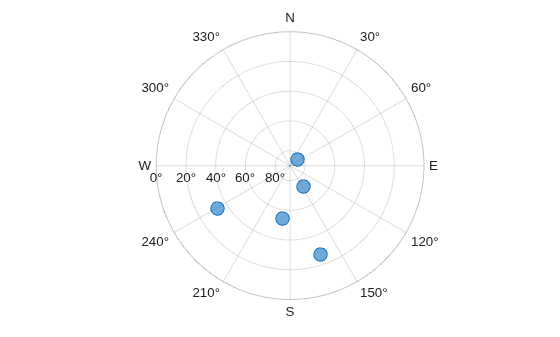
When position estimates are available, plot a sky plot and compare the true receiver position with the estimated position on geographic axes.
if exist("rxposest","var") && ~all(isnan(rxposest))
    [az,el] = lookangles(rxposest,satpos);
    figure
    skyplot(az,el)

    figure
    gx = geoaxes;
    hold(gx,"on")

    geoscatter(gx,rxpos(1),rxpos(2),40,"b","filled",DisplayName="True position")
    geoscatter(gx,rxposest(1),rxposest(2),40,"xr",LineWidth=1.5,DisplayName="Estimated position")

    legend(gx,Location="best")
    geobasemap(gx,"satellite")
end
Further Exploration
Change the receiver location, sampling frequency, or simulation duration to see how each setting affects the final position estimate. You can also try at different epoch time or RINEX file with more visible satellites.
Supporting Files
This example uses these helper files.
HelperQZSSWaveformGenerator —Generates QZSS L1C/A or L1C/B baseband waveformsHelperGNSSSignalAcquirer —Performs FFT-based parallel code-phase search acquisitionHelperGNSSSignalTracker —Implements PLL/FLL/DLL tracking loopsHelperGNSSChannel —Models propagation impairments (Doppler, delay, AWGN)HelperGPSLNAVDataDecode —Decodes LNAV subframe data into ephemeris parametersHelperGPSNAVDataEncode —Encodes LNAV navigation message bits from configurationHelperQZSSRINEX2Config —Maps RINEX ephemeris data to navigation configuration objectsHelperGPSNavigationConfig —Configuration object for LNAV navigation dataHelperGNSSConvertTime —Converts between QZSS week/TOW and datetimeHelperAddQZSSSatellite —Adds satellites to a satellite scenario from ephemerisHelperGNSSSatelliteStates —Computes satellite ECEF positions from broadcast ephemerisHelperGPSLNAVWordDecode —Decode each word of a subframe
References
[1] IS-QZSS-PNT-006, "Quasi-Zenith Satellite System Interface Specification: Satellite Positioning, Navigation and Timing Service," Cabinet Office, Government of Japan, July 11, 2024.
[2] NASA Earthdata | Broadcast Ephemeris Data Product

