S-Parameters in Parallel Link Projects
You can import S-Parameter data from a Touchstone file format (sNp files) into the libraries of the Parallel Link
Designer app. The import operation includes creating a wrapper and editing a port map
since there is no standard way to determine how nodes in a Touchstone file map to connections in the system. To place the S-Parameter from the library
in the schematic, click the S-Parameter (![]() ) button.
) button.
Import S-Parameters
To import S-Parameters into a project library, click Libraries > Import S-Parameter... from the app toolstrip. This launches two windows: Import S-Parameter File(s) and Select S-Parameter (Touchstone) Files dialog boxes.
In the Select S-Parameter (Touchstone) Files dialog box, select one or more Touchstone files to import in the library. Then use the Import S-Parameter File(s) dialog box to import the files and create port maps. You can also edit the port maps using the Port Map Editor dialog box.
When you import multiple files with the same number of ports, the app puts the wrapper files for the S-Parameters into a single file. This is default behavior as it simplifies the library structure and makes it easy to manage sweeps. You can deselect Merge Wrappers option in the Select S-Parameter (Touchstone) Files dialog box to turn off this default behavior.
After you finish importing the S-Parameter files, you can see the import results in the Import Log section of the Select S-Parameter (Touchstone) Files dialog box.
S-Parameter Port Maps
There is no standard way to map Touchstone file ports to the symbol pins. So, the app creates a port map for each imported Touchstone file by identifying the through paths and the differential pairs. The app finds the through paths by looking at the port to port loss at 50MHz and finding the smallest loss between the ports. The app also looks at the coupling between the through paths and considers the pairs with most coupling as differential pairs.
To view or modify the port map, launch the Edit S-Parameter File Port Maps dialog box by selecting Launch Edit Port Maps Editor option in the Select S-Parameter (Touchstone) Files dialog box. The port map editor can edit multiple files at once. Each file is in its own tab in the editor.
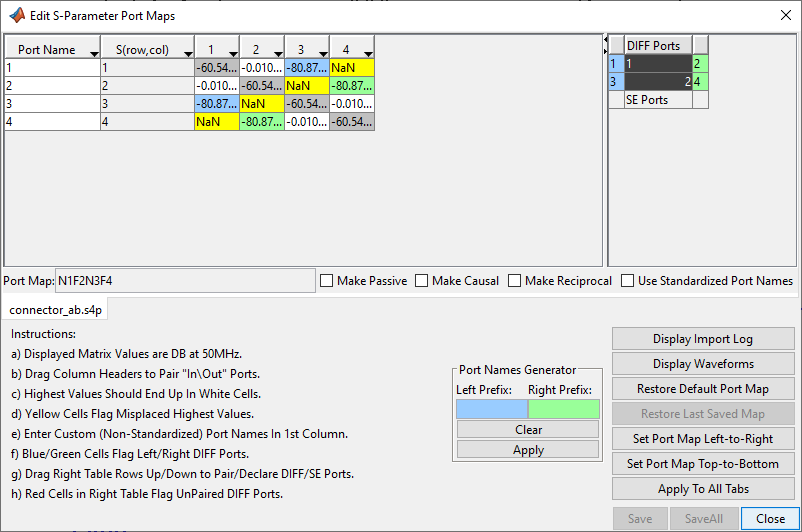
The table on the left shows the S-Parameter values in dB at 50MHz. The table on the right is the symbols view that shows how the ports maps to the schematic symbol. The lower part of the dialog box allows you to view the import log, launch the waveform viewer, restore to defaults and apply changes to the file being modified to all files.
The app determines through paths by finding the ports that have the smallest loss between them. In this case, the white cells are the cells with the smallest loss. The rows and columns in the table represent the port matrix of the S-Parameter block, so the upper left gray cell is the S11 value, and the white cell to its right is the S12 value. The through paths in this case are S12, S21, S34 and S43.
The app finds the differential pairs by looking at coupling between the through paths. The blue cells represent the left side differential ports. The green cells represent the right side differential ports. The Port Map field shows the port numbers and whether they are the near (N) or far (F) end of a through path. For example, N1F2N3F4 is an S-Parameter block with ports 1 and 3 on the near side and ports 2 and 4 on the far side, making the through paths 1 to 2 and 3 to 4.
You can change the order the table columns by clicking on a column header and dragging it left or right to the desired location. o You can also change the port order by clicking and dragging the blue or green ports on the right-hand side. o You can move ports from DIFF Ports to SE Ports by clicking and dragging as well.
Note
It is recommended that you always review the auto-generated port map.
By default the port names are the same as the port numbers. You can edit the names in the far left column of the table. You can also change the port names so that the through path is always from ports with odd numbers for names to ports with even numbers for names. To do this, select the Use Standardized Port Names option. This creates symbols with odd-numbered port names on the left and even-numbered port names on the right.
Combining S-Parameter Files
Combine Crosstalk S-Parameters
To analyze crosstalk in the Serial Link Designer app, you must use a model of the coupled interconnect. The apps can combine s4p files representing through, NEXT (near end crosstalk) and FEXT (far end crosstalk) paths into larger S-Parameter files for use in the pre-layout crosstalk analysis. You must import the s4p files into the libraries before combining them. This allows you to check the S-Parameters port map consistency for passivity, causality and reciprocity.
To combine the files, click Libraries > Combine S-Parameters. This launches a dialog box where you can specify the number of FEXT and NEXT aggressors. This determines the size of the resulting S-Parameter file.
After you specify the number of aggressors and click OK, the app launches the Combine S-Parameters dialog box. Here you can match the previously imported s4p files to their place in the combined S-Parameter file. Once you save the combined S-Parameter file to the library, you can place it on the schematic like any other S-Parameter.