Ciclo de trabajo de la forma de onda de pulso rectangular
Este ejemplo muestra cómo crear una forma de onda de pulso rectangular y medir su ciclo de trabajo. Considere una forma de onda de pulso rectangular como una secuencia de estados activado y desactivado. Un periodo de pulso es la duración total de un estado activado y desactivado. La anchura de pulso es la duración del estado activado. El ciclo de trabajo es la relación entre la anchura de pulso y el periodo de pulso. El ciclo de trabajo de un pulso rectangular describe la fracción de tiempo en la que el pulso está activado en un periodo de pulso.
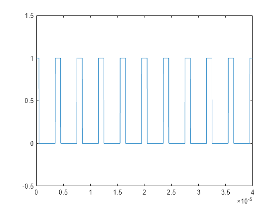
Cree un pulso rectangular muestreado a 1 gigahercio. El pulso está activado, o es igual a 1, durante 1 microsegundo. El pulso está desactivado, o es igual a 0, durante 3 microsegundos. El periodo de pulso es de 4 microsegundos. Represente la forma de onda.
Fs = 1e9;
t = 0:1/Fs:(10*4e-6);

pulsewidth = 1e-6;
pulseperiods = [0:10]*4e-6;

x = pulstran(t,pulseperiods,@rectpuls,pulsewidth);

plot(t,x)
axis([0 4e-5 -0.5 1.5])

Determine el ciclo de trabajo de la forma de onda utilizando dutycycle. Introduzca tanto la forma de onda de pulso como la tasa de muestreo para obtener el ciclo de trabajo. dutycycle devuelve un valor de ciclo de trabajo para cada pulso detectado.
D = dutycycle(x,Fs)
D = 1×9

    0.2500    0.2500    0.2500    0.2500    0.2500    0.2500    0.2500    0.2500    0.2500
En este ejemplo, el ciclo de trabajo para cada pulso detectado es idéntico y equivale a 0,25. Se trata del ciclo de trabajo previsto, porque el pulso está activado durante 1 microsegundo y desactivado durante 3 microsegundos en cada periodo de 4 microsegundos. Por lo tanto, el pulso está activado durante 1/4 de cada periodo. Expresado como porcentaje, equivale a un ciclo de trabajo del 25%.
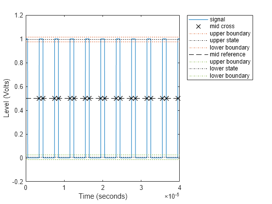
Llamar a dutycycle sin argumentos de salida genera una gráfica con todas las anchuras de pulso detectadas marcadas.
dutycycle(x,Fs);

Utilizando la misma tasa de muestreo y el mismo periodo de pulso, varíe el tiempo de activación del pulso (anchura de pulso) de 1 a 3 microsegundos en un bucle y calcule el ciclo de trabajo. Represente las formas de onda de pulso y visualice el valor del ciclo de trabajo en el título de gráfica para cada paso del bucle. El ciclo de trabajo aumenta de 0,25 (1/4) a 0,75 (3/4) a medida que aumenta la anchura de pulso.
nwid = 3;

for nn = 1:nwid
    x = pulstran(t,pulseperiods,@rectpuls,nn*pulsewidth);

    subplot(nwid,1,nn)
    plot(t,x)
    axis([0 4e-5 -0.5 1.5])

    D = dutycycle(x,Fs);
    title(['Duty cycle is ' num2str(mean(D))])
end
