Validating IP2/IP3 Using Complex Signals
This example shows how to use the RF Blockset™ Circuit Envelope library to run a two-tone experiment that measures the second- and third-order intercept points of an amplifier. The model computes the intercept points of the amplifier from the modulated signal power measured on each carrier, verifying the behavior of the RF Blockset system. These values are confirmed using the RF Budget Analyzer app and a measurement testbench.

System Architecture
The system consists of:
Two complex voltage sources connected in series. The first voltage source is modeled with Simulink® blocks, and the second with blocks from the RF Blockset circuit envelope library. In the Simulink Source subsystem, two series Sine Wave blocks model in-phase and quadrature components of the first tone. An Inport block assigns the Simulink signal to the carrier
fc1. In the RF Blockset Source subsystem, two series Sinusoid blocks model in-phase and quadrature voltage signals that modulate the carrierfc2.A resistor modeling the voltage source impedance.
An amplifier with input impedance, output impedance specified in the Main tab; output IP2, and output IP3 specified in the Nonlinearity tab.
An Outport block that probes the output voltage of the amplifier across a shunt Resistor block. The ordering of the output signals is determined by the ordering of the carriers specified in the Outport block dialog box.
A subsystem to compute running rms power levels at the input, IP2 and IP3 frequencies.
A subsystem to compute IP2 and IP3 intercept points [1].
The example model defines variables for block parameters using a callback function. To access model callbacks, select MODELING > Model Settings > Model Properties and click the Callbacks tab in the Model Properties window.
Running the Example
Type
open_system('simrfV2_carriers')at the Command Window prompt.Select Simulation > Run.
Output power and amplifier output intercept points are displayed on the right side of the model. The Calculate Power subsystem computes the power in dBm of each intermodulation product using a running root-mean-square (RMS) average.
Modeling Nonlinear RF Blockset Components
To model nonlinearities in the RF Blockset circuit envelope environment:
Place an Amplifier or Mixer block in your model.
Specify parameters that generate nonlinearities, such as IP2 and IP3, taking care to specify the convention or specify a polynomial directly in the Nonlinearity tab of the block dialog box.
Specify any additional carrier frequencies for simulation in the Configuration block. In this example, the Configuration block specifies a total of twenty five frequencies :
fc1andfc2, as the Fundamental Tones of the input signals; a Harmonic Order of 3 for each tone resulting in a complete set of second, third, fourth-order intermodulation products(second and third-order harmonic products included), and a partial set of fifth and sixth-order intermodulation products.
In order to calculate the power level of each envelope, the measured voltage signals are scaled with the inverse of the square root of the characteristic impedance. An additional scaling of 1/sqrt(2) in the Calculate Power subsystem normalizes the complex-valued output signal.
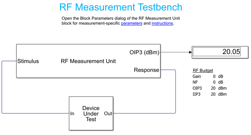
Validate Using Measurement Testbench
The same measurements can be performed using the RF Budget Analyzer app to automatically generate the model and testbench.
Open the RF Budget Analyzer app and specify an amplifier.
Define its OIP3. In this example, the OIP3 is set to 20 dB.
Click Export button and select Measurement Testbench to export the Amplifier element to testbench in RF Blockset.

Open Device Under Test to reveal the amplifier. Specify the IP2 value.
Select the RF Measurement Unit testbench and clear the Simulate noise (both stimulus and internal DUT) so that noise floor is below the IM signal level. This enables accurate OIP3 measurement.
Run the simulation and measure IP3.
Change the quantity to be verified to IP2 and rerun the simulation. Set IP3 to 25 dBm.

If you look under the mask of the testbench, you will find the logic to measure IP2 and IP3. This methodology is very similar to what is described in the initial model.
Reference
Kundert, Ken. "Accurate and Rapid Measurement of IP2 and IP3." The Designers Guide Community, Version 1b, May 22, 2002.
See Also
IIP3 Testbench | IIP2 Testbench