Multiphase Coupled Lines
R2026bMultiphase Coupled Lines block

To add a block to a model, double-click the canvas and start typing the block name. Then, select the block from the list.
Libraries:
Simscape /
Electrical /
Passive /
Lines
Description
The Multiphase Coupled Lines block models magnetically coupled multiphase lines. Each line has a self inductance, a series resistance, and an optional parallel conductance. In addition, there is a mutual inductance, a mutual resistance, and an optional mutual capacitance between each pair of lines.
To model magnetic coupling of a single pair of lines, use the Coupled Lines (Pair) block. To model magnetic coupling of three lines, use the Coupled Lines (Three-Phase) block.
The Multiphase Coupled Lines block allows you to model the
lines with either balanced or unbalanced impedance. To choose whether to model balanced or
unbalanced impedance, set the Parameterization parameter to
Balanced impedance or General
impedance, respectively.
Equations
When you set the Parameterization parameter to
Balanced impedance, the coupled lines are balanced and the
resistance, inductance, and capacitance matrices are
where:
Rs is the self resistance of the transmission line per phase.
Rm is the line-line mutual resistance.
Ls is the self inductance of the transmission line per phase.
Lm is the line-line mutual inductance.
Cs is the self capacitance of the transmission line per phase.
Cm is the line-line mutual capacitance.
When you set the Parameterization parameter to General
impedance, the coupled lines are general or unbalanced, and you must
directly specify the resistance, inductance, and capacitance matrices by using the
Line inductance matrix, Line resistance matrix,
and Capacitance matrix parameters.
If you set the Model capacitance parameter to Exclude
capacitance, then the block uses these defining equations for the coupled lines:
where:
V1 is the voltage vector at port 1.
V2 is the voltage vector at port 2.
I1 is the current vector flowing into port 1.
I2 is the current vector flowing into port 2.
IL is the current vector flowing through the inductors.
R is the resistance matrix.
L is the inductance matrix.
If you set the Model capacitance parameter to Include
capacitance at one port, then the block uses these defining equations for
the coupled lines:
where C is the capacitance matrix.
If you set the Model capacitance parameter to Include
capacitance at both ports, then the block uses these defining equations for
the coupled lines:
Assumptions and Limitations
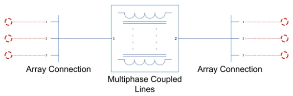
The 1 and 2 ports of this block represent multiple nodes as single ports. The number of nodes inside each port depends on the value of the Number of phases parameter. To access each connection port on both sides of the block, use the Array Connection block.
Ports
Conserving
Parameters
Extended Capabilities
Version History
Introduced in R2026b

