Find Periodic Operating Point for Switching Boost Converter Model
This example shows how to find a periodic steady-state operating point for a switching power electronics circuit modeled using Simscape™ and Simscape Electrical™ components. More specifically, this example finds a periodic operating point for an open-loop boost converter model.
To find a steady-state operating point:
Select a periodic signal in the model to monitor.
Specify the known period of the signal.
Specify a convergence tolerance for the periodic signal values.
Calculate the operating point using these specifications.
You can then use the operating point for additional analysis, such as simulation and frequency response estimation.
When you use this approach for finding a periodic operating point, you cannot specify additional trimming specifications, such as known state, input, and output values for any signals in the model.
Boost Converter Model
The plant model is an open-loop boost converter derived from the scdboostconverter model. For this example, the model does not include a voltage controller in a feedback loop.
mdl = "scdboostconverterOpenLoop";
open_system(mdl)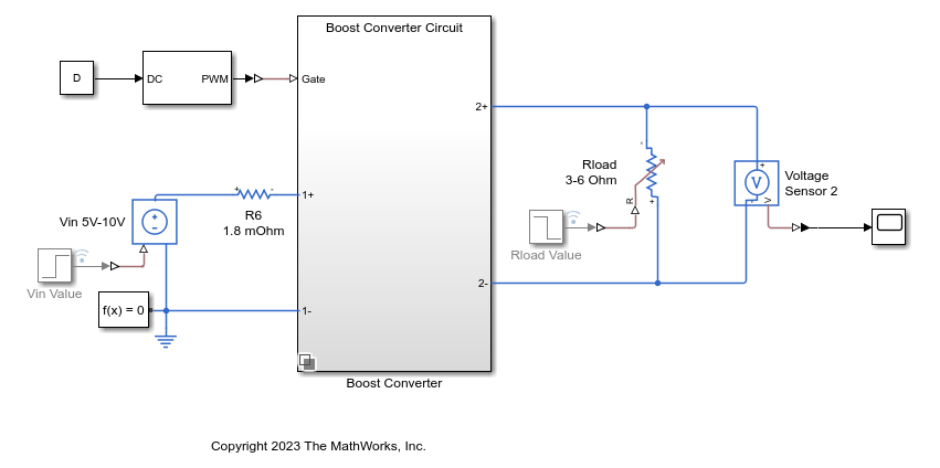
The boost converter uses a PWM generator and takes a constant duty cycle D to convert the input voltage Vin to an output voltage over the load resistor Rload. Simulate the model to observe the initial transient that moves from the zero initial condition to the periodic steady state.
tic
sim(mdl,StopTime="0.05");
toc
Elapsed time is 11.019705 seconds.
The output voltage of the boost converter converges to a periodic steady state after an initial transient.
View the initial transient in the output voltage over Rload.
open_system(mdl + "/Scope")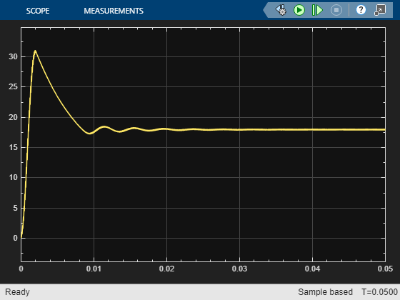
Close the scope.
close_system(mdl + "/Scope")While you can use such a simulation to find a steady-state operating point, the simulation can take a long time for fully switching circuit models and you must manually confirm that the system is actually in a periodic steady-state condition.
Define Periodic Operating Point Specification
Create an operating point specification for the model using the operspec function.
opspec = operspec(mdl);
When finding a periodic operating point, you can monitor one signal to determine when the model converges to a periodic steady state. To find a periodic operating point, first add an output specification for the periodic signal. For this example, add an output specification for the output of the PS-Simulink Converter block, which corresponds to the output of the voltage sensor.
opspec = addoutputspec(opspec,mdl + "/PS-Simulink Converter",1);You must add this output specification to a Simulink signal. The PS-Simulink Converter block converts the Simscape voltage signal to a Simulink signal.
Specify the known period for the output signal. For this example, use a period of 5e-5 sec, which is the period of the PWM generator.
opspec.Outputs.Period = 5e-5;
Specify a tolerance for the periodic signal convergence. This value is the tolerance for determining whether two points in the signal, separated by one period, are equal.
opspec.Outputs.PeriodicTolerance = 1e-6;
View the final output specification for the periodic signal.
opspec.Outputs
ans =
        y               Known              Min               Max             Period       PeriodicTolerance
_________________ _________________ _________________ _________________ _________________ _________________

(1.) scdboostconverterOpenLoop/PS-Simulink Converter
        0               false             -Inf               Inf              5e-05             1e-06
When you monitor the periodic signal, the software ignores the Known, Min, and Max specifications for the signal.
Find Operating Point
To find an operating point that meets these specifications, use the findop function. The software simulates the model from its initial condition and determines when the monitored signal is in a periodic steady state within the specified tolerance. Using the findop function with a periodic operating point specification is significantly faster than simply simulating the model to a specified snapshot time.
tic
[op,opreport] = findop(mdl,opspec);
 Operating point search report:
---------------------------------
opreport =
 Operating point search report for the Model scdboostconverterOpenLoop.
 (Time-Varying Components Evaluated at time t=0.0360015)

Periodic steady-state specification includes a nonzero, finite period. Steady-state signal converged at time 0.036001 seconds.
States:
----------
   Min         x         Max       dxMin        dx       dxMax
__________ __________ __________ __________ __________ __________

(1.) scdboostconverterOpenLoop.Boost_Converter.Boost_Converter_Circuit.C1_1480uF.vc
   -Inf     17.8918      Inf         0          0          0
(2.) scdboostconverterOpenLoop.Boost_Converter.Boost_Converter_Circuit.C1_1480uF.i
   -Inf     11.8161      Inf         0          0          0
(3.) scdboostconverterOpenLoop.Boost_Converter.Boost_Converter_Circuit.Diode.Diode.i_diode
   -Inf     14.8138      Inf         0          0          0
(4.) scdboostconverterOpenLoop.Boost_Converter.Boost_Converter_Circuit.Diode.Diode.p.v
   -Inf     18.8011      Inf         0          0          0
(5.) scdboostconverterOpenLoop.Boost_Converter.Boost_Converter_Circuit.Diode.Diode.threshold
   -Inf     14.8138      Inf         0          0          0
(6.) scdboostconverterOpenLoop.Boost_Converter.Boost_Converter_Circuit.L1_20uH.i_L
   -Inf      14.814      Inf         0          0          0
(7.) scdboostconverterOpenLoop.Boost_Converter.Boost_Converter_Circuit.MOSFET.mosfet_equation.i
   -Inf    1.8801e-08    Inf         0          0          0
(8.) scdboostconverterOpenLoop.Boost_Converter.Boost_Converter_Circuit.MOSFET.diode.Diode.threshold
   -Inf     -18.8021     Inf         0          0          0
(9.) scdboostconverterOpenLoop/PWM Generator/Carrier counter/Integrator with Wrapped State (Discrete or Continuous)/Discrete/Integrator
   -Inf     1.5e-06      Inf         0          0          0
(10.) scdboostconverterOpenLoop/PWM Generator/Carrier counter/Integrator with Wrapped State (Discrete or Continuous)1/Discrete/Integrator
   -Inf     1.5e-06      Inf         0          0          0
(11.) scdboostconverterOpenLoop/Simulink-PS Converter1
   -Inf        0         Inf         0          0          0
   -Inf        6         Inf         0          0          0
(12.) scdboostconverterOpenLoop/Simulink-PS Converter2
   -Inf        0         Inf         0          0          0
   -Inf        0         Inf         0          0          0
(13.) scdboostconverterOpenLoop/Simulink-PS Converter3
   -Inf        0         Inf         0          0          0
   -Inf        5         Inf         0          0          0

Inputs: None
----------

Outputs:
----------
  Min      y      Max
_______ _______ _______

(1.) scdboostconverterOpenLoop/PS-Simulink Converter
 -Inf   17.9863   Inf
toc
Elapsed time is 5.057333 seconds.
By default, findop displays an operating point search report in the command window. This report is also available in the opreport output argument.
The report shows that the model converges to a steady-state condition in about 0.036 seconds.
The operating point search report contains the value of the output signal at this convergence time.
opreport.Outputs.y
ans =
17.9863
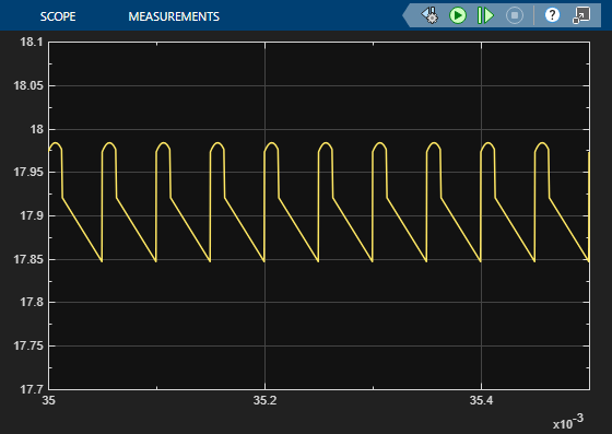
To confirm that the output signal is periodic at this time, you can zoom in on the original simulation output signal. At the computed convergence time, the signal is periodic.
Set Operating Point as Model Initial Condition
To analyze your model at the computed steady-state operating point, you must set the initial state and input values of the model to the corresponding values from the operating point. Since there are no root-level input ports in the model, the computed operating point contains only state values.
Obtain the initial state values from the operating point.
xInitial = getstatestruct(op);
Set the initial state values in the model.
set_param(mdl,"LoadInitialState","on","InitialState","xInitial")
If the model has root-level input ports, you set the initial input values in a similar manner.
uInitial = getinputstruct(op);
set_param(mdl,"LoadExternalInput","on","ExternalInput","uInitial")
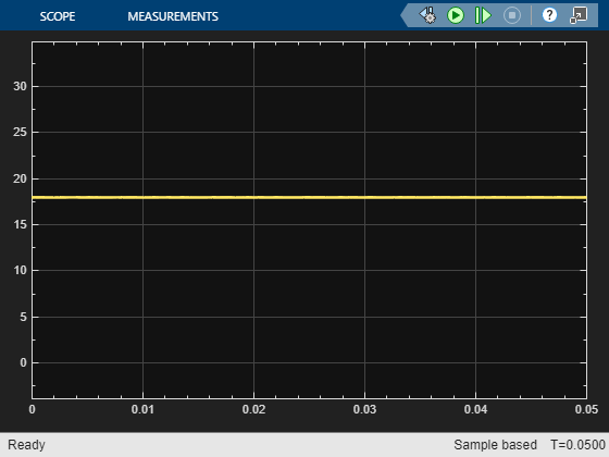
Simulate the model and view the output voltage signal, which is at a periodic steady state.
sim(mdl,StopTime="0.05");
open_system(mdl + "/Scope")