Filtros
Utilice estos ejemplos para aprender a diseñar filtros de procesamiento de señales para eliminar o mejorar componentes de frecuencia.
Ejemplos destacados
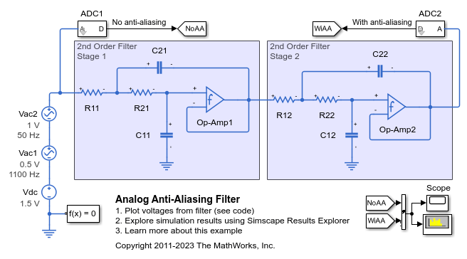
Filtro analógico antialiasing
Este ejemplo muestra la implementación analógica de un filtro antialiasing para utilizarlo con un convertidor de A a D. La frecuencia de corte del filtro está establecida en 500 Hz para que coincida con la frecuencia de muestreo de 1 kHz del convertidor de A a D. La señal de prueba incorpora una sinusoide de 50 Hz deseada y un componente de mayor frecuencia a 1.100 Hz que no puede capturarse con una frecuencia de muestreo de A a D de 1 kHz. El scope muestra la señal capturada sin y con antialiasing. Con el filtro antialising, la amplitud de la onda sinusoidal de 50 Hz se mide correctamente con una amplitud de 1 y una potencia correspondiente de 0,5 W, es decir, 27 dBm para una carga de referencia de 1 ohmio.

Band-Pass Filter Using Three Mutually-Coupled Inductors
An implementation of a band-pass filter using three mutually-coupled inductors. The model can be used to validate filter parameters which are chosen to provide a band-pass centered on 100MHz. A band-limited noise source is up-shifted by a 100MHz oscillator and applied to the filter. The response is then down-shifted by the oscillator. The model StopFcn callback takes FFTs of the source and response and estimates the filter frequency response.

Controllable Phase Shifter
An implementation of a first order phase shifting filter. The filter is characterized by the transfer function H(s) = (sC - gm1)/(sC + gm1). Double-click on the Set Design Parameters block to set the desired phase shift, amplitude of the input signal, and the frequency of the input signal. The block mask calls a function which sets the parameter values in the model workspace.

Fourth-Order Sallen-Key Lowpass Filter
An implementation of a fourth-order Sallen-Key low-pass filter using Operational Amplifiers (OPAs). The filter design parameters, cut-off frequency (f1) and DC gain (K), are specified by double-clicking on the Set Design Parameters block. Pass-band ripple is predefined to be 1dB using a Chebyshev response. The block mask calls a function which sets the parameter values in the model workspace.

Low-Pass Filter Using Operational Transconductance Amplifiers
Model a second-order active low-pass filter. The filter is characterized by the transfer function H(s) = 1 / ( (s/w1)^2 + (1/Q)*(s/w1) + 1 ) where w1 = 2*pi*f1, f1 is the cut-off frequency and Q is the quality factor. Double-click on the Set Design Parameters block to set parameters f1 and Q. The block mask calls a function which sets the parameter values in the model workspace.