Vehicle Climate Control System
This example models a vehicle climate control system. This system uses a Stateflow® controller to manage heating, air conditioning, and blower functions. To see an example of how to integrate this system with a plant model, see Vehicle Electrical and Climate Control Systems.
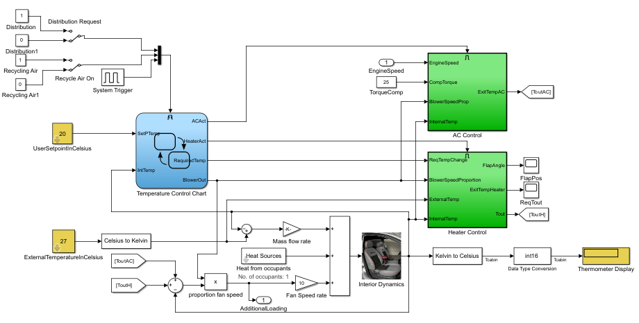
Open the model sldemo_auto_climatecontrol.slx.
open_system("sldemo_auto_climatecontrol.slx")Climate Control System
You can specify two inputs to the system:
The
UserSetpointInCelsiussubsystem block represents the target temperature inside the vehicle.The
ExternalTemperatureInCelsiussubsystem block represents the temperature outside the vehicle.
The system outputs the temperature reading from a sensor behind the head of the driver, which reflects the temperature that the driver experiences. After simulation, this reading appears in the Display block, Thermometer Display.
Stateflow Controller
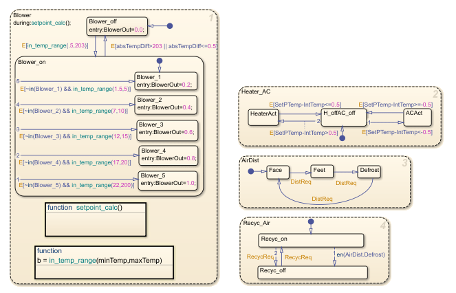
The Temperature Control chart manages supervisory control logic implementation. There are four different child states that run simultaneously to control different aspects of the climate inside the car.
The
Heater_ACstate manages heating and cooling cycles.The
Blowerstate controls fan speed.The
AirDiststate controls air distribution.The
Recyc_Airstate controls air recycling.
The Heater_AC state manages temperature control by transitioning between heating, idle, and cooling modes. Heating turns on when the setpoint exceeds the internal temperature by more than 0.55 °C and turns off when the difference is 0.5 °C or less. Similarly, cooling turns on when the internal temperature exceeds the setpoint by more than 0.55°C and turns off when the difference is 0.5 °C or less. The controller uses a 0.05 °C hysteresis band from 0.5 °C to 0.55 °C to avoid rapid switching between heating and cooling.
In the Blower state, the system adjusts the fan output based on the temperature difference. The system turns the blower off when the absolute temperature difference is below eps or too large. The blower runs only within the defined intermediate temperature range, allowing efficient and proportional airflow control during temperature regulation.
The state AirDist responds to driver switch inputs for air blower output.
When the driver activates defrost mode, the Recyc_Air state disables air recycling.
Heater and Air Conditioner Models
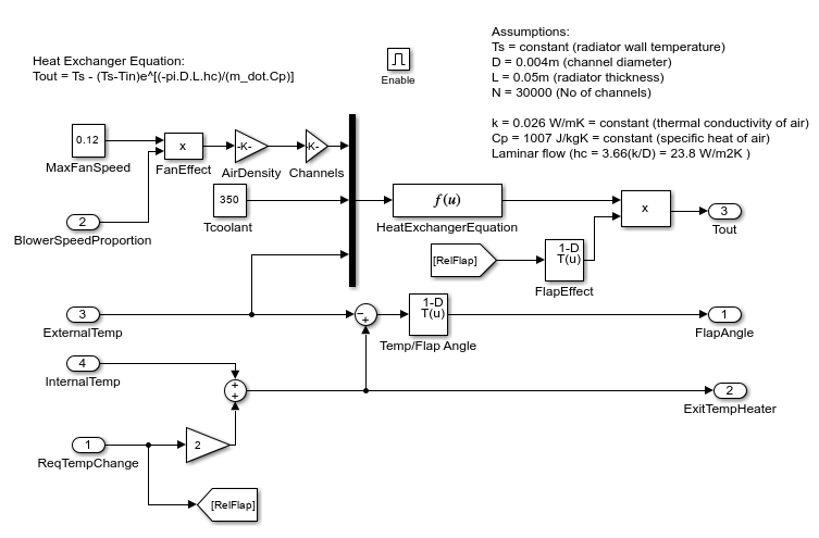
The heater model is built from this equation for a heat exchanger:
Tout = Ts - (Ts-Tin)e^[(-pi*D*L*hc)/(m_dot*Cp)]
where:
Ts = constant (radiator wall temperature)
D = 0.004m (channel diameter)
L = 0.05m (radiator thickness)
N = 30000 (Number of channels)
k = 0.026 W/mK = constant (thermal conductivity of air)
Cp = 1007 J/kgK = constant (specific heat of air)
Laminar flow (hc = 3.66(k/D) = 23.8 W/m2K )
The model considers the effect of the heater flap. Similar to the blower operation, the heat flap output is proportional to the difference between the setpoint temperature and the current temperature. The greater the temperature difference, the more the heat flap opens and increases the heating effect.
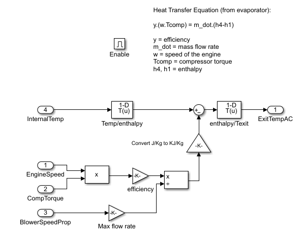
The air conditioner (AC) system is one of the two places where the climate control model interfaces with the vehicle electrical system model. The compressor loads the vehicle engine when the AC system is active. The model implements this equation to determine the AC final temperature:
y*(w*Tcomp) = m_dot*(h4-h1)
where:
y = efficiency
m_dot = mass flow rate
w = speed of the engine
Tcomp = compressor torque
h4, h1 = enthalpy
For the AC system, the model implements bang-bang control. The engine speed and compressor torque control the air temperature that exits the AC.