PX4 Hardware-in-the-Loop (HITL) Simulation with Fixed-Wing Plant in Simulink
This example shows how to use the UAV Toolbox Support Package for PX4® Autopilots to verify the controller design by deploying the design on the Pixhawk® hardware board. This is done in HITL mode with fixed-wing UAV Dynamics contained in Simulink®.
This example provides a reference model that helps you to design a flight controller algorithm to perform take-off, waypoint-following, loitering, and landing for a fixed-wing UAV plant model. Additionally, the example also provides a plant model which captures aspects such as aerodynamics, propulsion, ground contact, and sensors. This example demonstrates three workflows.
Follow a mission provided from QGC.
Manual Control with RC Joystick. For more information, see PX4 Hardware-in-the-Loop (HITL) Simulation with Manual Control for Fixed-Wing Plant in Simulink.
Execute a mission hardcoded in Simulink. For more information, see PX4 Hardware-in-the-Loop (HITL) Simulation with Fixed-Wing Plant and Hardcoded Mission in Simulink.
For information on fixed-wing plant model architecture, guidance logic, and conventions, see Fixed-Wing Plant and Controller Architecture.
Prerequisites
If you are new to Simulink, watch the Simulink Quick Start video.
Go through the PX4 Hardware-in-the-Loop System Architecture document to understand the physical connections required to setup the Pixhawk and Simulink for HITL Simulation.
Configure and set up Pixhawk in HITL mode. For more information, see Setting up PX4 Autopilot in Hardware-in-the-Loop (HITL) Mode from QGroundControl.
Setup the PX4 Firmware as mentioned in Set Up PX4 Firmware for Hardware-in-the-Loop Simulation. In the Select a PX4 Autopilot and Build Target screen, select any Pixhawk Series board as the PX4 Autopilot board from the drop-down list. This example uses Pixhawk 4.
Required Third-Party Software
Required Hardware
Pixhawk Series flight controller
Micro USB (Universal Serial Bus) type-B cable
Micro-SD card
Serial-to-USB FTDI converter
Mini USB cable for FTDI
Pixhawk serial port connectors
Run HITL Simulation
Note: Avoid running this example on a virtual machine. The virtual machine might display an error saying "unable to pace at specified rate" and the drone might crash.
Step 1: Make Hardware Connections and Set Up the Pixhawk in HITL Mode
This diagram shows the HITL setup and the physical communication between various modules.

1. Connect your Pixhawk board to the host computer using the USB cable.
2. Configure the Pixhawk board in HITL mode as described in Setting up PX4 Autopilot in Hardware-in-the-Loop (HITL) Mode from QGroundControl.
3. Set up the PX4 Firmware as described in Set Up PX4 Firmware for Hardware-in-the-Loop Simulation.
Step 2: Open MATLAB Project
1. Open MATLAB®.
2. Open the px4demo_HardwareInLoopWithSimulinkFixedWingPlant MATLAB project.
3. Once you open the project, click the Project Shortcuts tab on the MATLAB toolstrip and click Launch Autonomous Control Model to launch the FixedWingGNC controller.

4. In the Project Shortcuts tab, click Launch UAV Dynamics to launch the Simulink plant model named UAV_Dynamics_Autopilot_Communication.

5. In the Simulink plant model, set the serial ports in MAVLink Bridge Source and MAVLink Bridge Sink blocks.
Step 3: Configure Simulink Controller Model for HITL Mode
1. The controller model is configured to run in HITL mode. If you are not using this example model, follow the instructions as described in Configure Simulink Model for Deployment in Hardware-in-the-Loop (HITL) Simulation.
Note: These steps are not required in the pre-configured model. Complete these steps if you have changed the hardware or not using the pre-configured model.
2. PX4 PWM Output block does not work for targets such as Uvify IFO-S board. If you want to deploy the controller to Uvify IFO-S or if you want to allow PX4 to handle the mixing aspect, then select PX4 Mixer and actuator_controls_0 topic variant by setting the following parameter.
useCustomMixer = false;
This deploys the controller code on the Pixhawk hardware and launches the QGroundControl (QGC).
Note: If you are using Ubuntu, QGC might not launch automatically. To launch QGC, open Terminal and go to the folder where QGC is downloaded and run the following command:
./QGroundControl.AppImage|
Step 4: Run the UAV Dynamics Model, Upload Mission from QGroundControl and Fly UAV
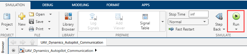
1. In the Simulink toolstrip of the Plant model (UAV_Dynamics_Autopilot_Communication), on the Simulation tab, click Run to simulate the model.
2. Set the parameter COM_DISARM_PRFLT value to -1, in QGC.
3. In the QGC, navigate to the Plan View.
4. This example provides a preplanned mission SampleMission.plan that you can upload to QGC. In the QGC, navigate and select SampleMission.plan file available in data folder of the MATLAB project.
After you upload the plan, the mission is visible in QGC.
5. Click Upload button in the QGC interface to upload the mission from QGroundControl.
6. Navigate to Fly View to view the uploaded mission.
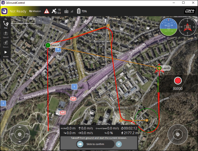
7. Start the mission in QGC. The UAV should follow the mission path.
After the mission is started, the drone takes off and follows the set of waypoints from QGC. A sample screen is shown here.
Other Things to Try
Try running complex missions from QGC. A sample survey mission trajectory is shown below.

Add wind disturbances to the plant model.
You can also select a web site from the following list:
Americas
- América Latina (Español)
- Canada (English)
- United States (English)
Europe
- Belgium (English)
- Denmark (English)
- Deutschland (Deutsch)
- España (Español)
- Finland (English)
- France (Français)
- Ireland (English)
- Italia (Italiano)
- Luxembourg (English)
- Netherlands (English)
- Norway (English)
- Österreich (Deutsch)
- Portugal (English)
- Sweden (English)
- Switzerland
- United Kingdom (English)