UVify IFO-S Autopilot and NVIDIA Jetson in Hardware-in-the-Loop (HITL) Simulation in Simulink
This example shows how to use the UAV Toolbox Support Package for PX4® Autopilots to deploy and verify algorithms on UVify IFO-S Drone, with NVIDIA® Jetson™ as Onboard computer.
This example shows you how to:
Deploy a flight control algorithm modeled in Simulink® to UVify IFO-S Autopilot.
Deploy an autonomous algorithm to NVIDIA Jetson.
Enable Scenario visualization in Unreal Engine®.
Perform HITL Simulation of UAV Dynamics and sensors.
Limitation: The Unreal Engine simulation environment is supported only on Microsoft® Windows® system. If you are using a Linux® system, skip adding the 3D scenario simulation step and you will still be able to complete this example.
Prerequisites
If you are new to Simulink, watch the Simulink Quick Start video.
Go through the PX4 Hardware-in-the-Loop System Architecture document to understand the physical connections required to setup the Pixhawk® and Simulink for HITL Simulation.
Configure and set up Pixhawk in HITL mode. For more information, see Setting Up PX4 Autopilot in Hardware-in-the-Loop (HITL) Mode from QGroundControl.
Set up the PX4 Firmware as mentioned in Set Up PX4 Firmware for Hardware-in-the-Loop (HITL) Simulation. In the Select a PX4 Autopilot and Build Target screen, select a Pixhawk Series board as the PX4 Autopilot board from the menu. This example uses UVify IFO-S.
To get familiar with the cosimulation framework for UAVs, see Unreal Engine Simulation for Unmanned Aerial Vehicles.
Required Third-Party Software This example requires the third-party software QGroundControl (QGC).
Required Hardware To run this example, you need this hardware:
UVify IFO-S
Micro USB type-B cable
Micro-SD card
NVIDIA Jetson & power adaptor (recommended)
Development computer configured with MATLAB® supported GPU, as shown in GPU Computing Requirements (Parallel Computing Toolbox). It is recommend to use GPU with compute capability of more than 5.
Workflow to Run Model on NVIDIA Jetson Along with Pixhawk in HITL Mode
This diagram illustrates the PX4 and NVIDIA Jetson HITL setup and the physical communication between various modules.
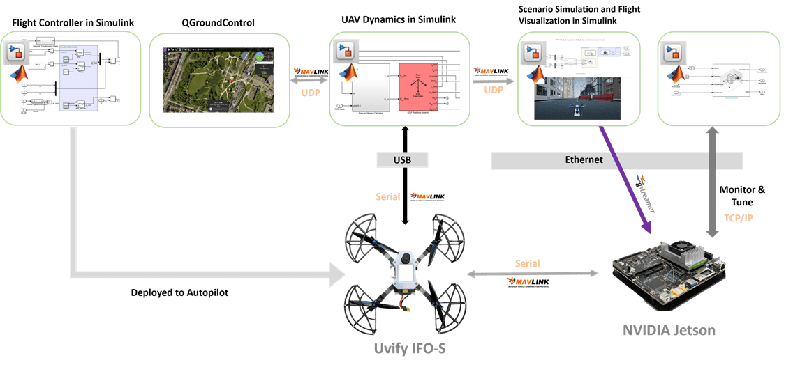
This example uses four Simulink models.
Flight Controller to be deployed on PX4 Autopilot
UAV Dynamics and sensor simulation
Autonomous algorithm to be deployed on NVIDIA Jetson
Flight visualization with Unreal Engine Simulation for Unmanned Aerial Vehicles
To avoid performance degradation in MATLAB due to three different Simulink models running at the same time, open three sessions of the same version of MATLAB.
In the first session of MATLAB, the Flight Controller is deployed on Autopilot and the UAV Dynamics model runs on the development computer communicating with Autopilot.
In the second session of MATLAB, the Simulink model for flight visualization with Unreal Engine Simulation runs. You can skip this if you choose to not add the flight visualization.
In the third session of MATLAB, the Simulink model for NVIDIA Jetson communicates with MATLAB on the development computer using Monitor & Tune Simulation.
Step 1: Make Hardware Connections and Set Up the UVify IFO-S Drone in HITL Mode
1. Connect your Autopilot board to the development computer using the USB cable.
2. Configure the Pixhawk board in HITL mode as documented in Setting Up PX4 Autopilot in Hardware-in-the-Loop (HITL) Mode from QGroundControl.
3. Set up the PX4 Firmware as mentioned in Set Up PX4 Firmware for Hardware-in-the-Loop (HITL) Simulation.
4. Set up and configure your NVIDIA Jetson on a network using MATLAB Coder Support Package for NVIDIA Jetson and NVIDIA DRIVE Platforms (MATLAB Coder).
Tip: Power your NVIDIA Jetson using a separate A/C adapter so that the Autopilot can be independently powered On/Off without rebooting NVIDIA Jetson.
Step 2: Open First Session of MATLAB and the MATLAB Project
The support package includes an example MATLAB project having the PX4 flight controller and the UAV to follow the mission set in the QGroundControl (QGC).
1. Open MATLAB.
2. Open the example project by executing this command at the MATLAB command prompt:
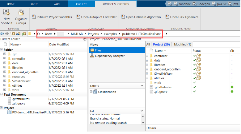
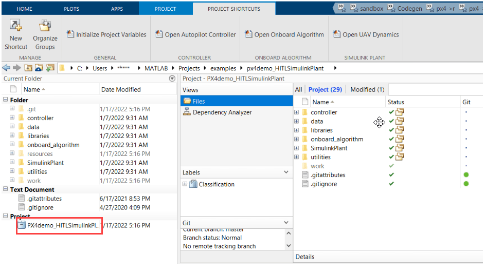
openProject('px4demo_HITLSimulinkPlant')
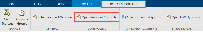
3. Once the Simulink project is open, click the Project Shortcuts tab on the MATLAB window and click Open Autopilot Controller to open PX4 Controller named Quadcopter_ControllerWithNavigation.

4. Navigate to the Navigation subsystem. This is a variant subsystem with guidanceType as the variant control variable. Define guidanceType = 1 in the base workspace to choose the navigation subsystem for this example.
5. In the Project Shortcuts tab, click Open UAV Dynamics to open the Simulink UAV Dynamics model named UAV_Dynamics_Autopilot_Communication.

6. Double-click the MAVLink Bridge source and sink blocks and set the serial port of autopilot board.
7. Add a local development computer connection for flight visualization in MAVLink Bridge Source block. Set the port to 25000.

8. Copy the MATLAB Project Path to clipboard.
Step 3: Configure Simulink Controller Model for HITL Mode
1. Follow the instructions in Configure Simulink Model for Deployment in Hardware-in-the-Loop (HITL) Simulation. Set Hardware Board to UVify IFO-S.
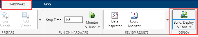
2. In the Simulink model window toolstrip, on the Hardware tab, click Build, Deploy & Start for the controller model Quadcopter_ControllerWithNavigation.
The code is generated for the controller model and automatically deployed to the autopilot board.
After the deployment is complete, QGroundControl is automatically opened.
Note: If you are using Ubuntu®, QGC might not open automatically. To open QGC, open Terminal and go to the location where QGC is downloaded and run this command:
./QGroundControl.AppImage
Step 4: Open Second Session of MATLAB and Open the Flight Visualization Model
Note: Skip this step if you choose not to use flight visualization with PX4 HITL.
1. Open the second instance of the same MATLAB version. In this MATLAB session, the Simulink model for scenario simulation and flight visualization using unreal environment runs.
Ensure that your development PC is configured with MATLAB supported GPU (GPU with compute capability of more than 5).
2. Open the project by executing this command at the MATLAB command prompt:
openProject('px4demo_HITLSimulinkPlant')
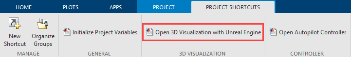
3. Once the Simulink project is open, in the MATLAB window, on the Project Shortcuts tab, click Open 3D Visualization with Unreal Engine to open the onboard model Unreal_3DVisualization.
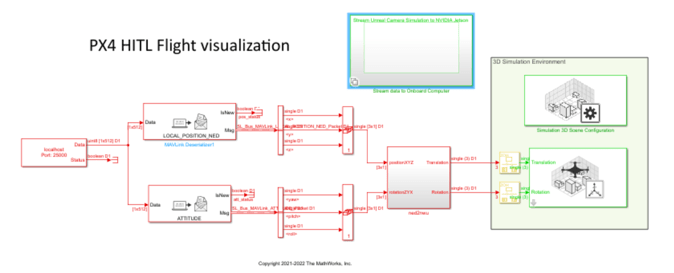
In this model, the MAVLink data from the PX4 Autopilot is received over UDP (port : 25000) and is used to decode the position and attitude data of the UAV. After coordinate conversion, it is then passed to the Simulation 3D UAV Vehicle block for flight visualization.
4. Enable the streaming of simulated depth sensor data in NVIDIA Jetson by setting the variable enableOnboardStreaming to 1.
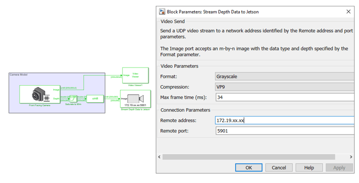
5. The Simulation 3D Camera block provides the Camera image from the Unreal environment. In this example you stream the depth images from the camera block to NVIDIA Jetson using Video Send block. Double-click block to open the block Parameters dialog box. Add the IP address of onboard computer (NVIDIA Jetson) in the dialog box and click OK.
6. On the Simulation tab, click Run to simulate the model. Once the model starts running, the Unreal simulation environment opens. A sample screen is shown below.

Step 5: Open Third Session of MATLAB and the Onboard Model
1. Open the third instance of the same MATLAB version.
2. Navigate to the project path previously copied in Step 2 in current MATLAB.

3. Click on the .prj file to open the same project in current MATLAB.
4. In the Project Shortcuts tab, click Open Onboard Algorithm to open the onboard model Onboard_Autopilot_Communication.

This model implements the PX4 path planning interface using MAVLink Serializer and MAVLink Deserializer blocks. For more information, see PX4 Path Planning Interface. The MAVLink messages that are exchanged as part of this interface are shown in this figure.
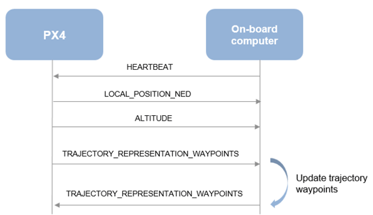
5. This example provides a basic onboard logic, which is sending back the received waypoint as the updated waypoint. Consider designing your own onboard logic after completing this basic example.

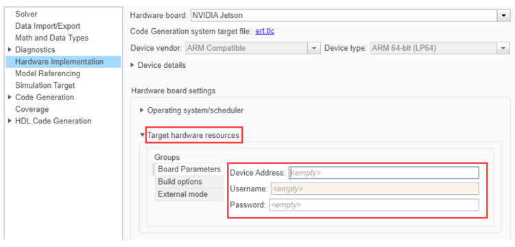
6. Navigate to Target hardware resource > Board Parameters, and enter the IP address of the NVIDIA Jetson and your login credentials.
7. This example uses MAVLink over serial ports to communicate between the Jetson and autopilot board. Activate the serial port variant by setting this workspace variable.
onboardMAVLinkSource = 1
8. Disable third party tools that might use the serial ports on Jetson such as MAVLink router.
Open QGC and set the following parameters to use the existing serial link between Jetson and UVify autopilot. For more information on UVify serial ports, see Serial Port Names and Corresponding Labels on PX4 Flight Controller Boards.
MAV_0_MODE = onboard
MAV_0_CONFIG = TELEM1
SER_TEL1_BAUD = 230400 8N1
9. Configure the Network Video Receive block to receive the depth data from Unreal environment. Note that the port number and compression parameters in the Network Video Receive block are same as those of the corresponding Video Send block streaming camera image from Unreal Engine.
Note: If you choose not to use flight visualization with PX4 HITL, comment the Network Video Receive block.
10. In the Simulink model window toolstrip, on the Hardware tab, in the Run on Hardware section, click Monitor & Tune.
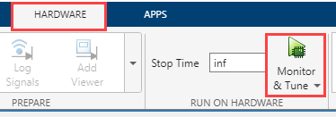
The code generator produces code for the controller model and Simulink deploys the same to NVIDIA Jetson. NVIDIA Jetson starts communicating with the development computer over Monitor & Tune Simulation.
Note: Make sure that no other models deployed from Simulink are running in NVIDIA Jetson. If you are unable to verify this, reboot the Pixhawk hardware board before starting the deployment.
The algorithm in NVIDIA Jetson also communicates with the plant model UAV_Dynamics_Autopilot_Communication over UDP.
Step 6: Run the UAV Dynamics Model, Upload Mission from QGroundControl and Fly the UAV
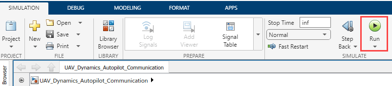
1. In the Simulink toolstrip of the plant model (UAV_Dynamics_Autopilot_Communication), on the Simulation tab, click Run to simulate the model.
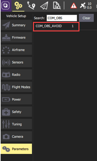
2. Set the PX4 parameter COM_OBS_AVOID enabling the PX4 path planning interface. Navigate to Parameters from the main menu and set the COM_OBS_AVOID parameter value to 1.
3. In the Parameters tab, set the COM_DISARM_PRFLT parameter value to -1.
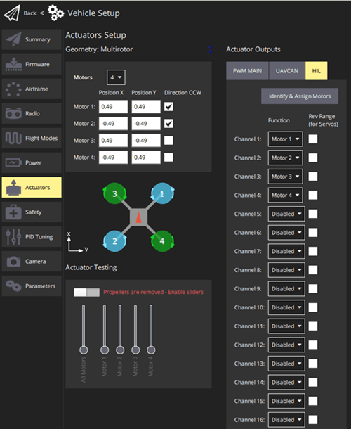
2. Configure the actuators in QGC. For more information, see Configure and Assign Actuators in QGC.
4. In the QGC, navigate to the Plan View.
Troubleshooting
While Simulating the visualization model in Step 4, you might get STD exception errors such as, "some module could not be found". To fix this issue, change the compiler to Microsoft Visual C++ 2019 by using the
mex -setup c++command.
The warning "Avoidance system not available" might be displayed when starting a mission. The warning occurs because the communication between NVIDIA Jetson and PX4 HITL is not established.
Check that development computer and NVIDIA Jetson are connected to the same network. Try pinging NVIDIA Jetson from the development computer and vice versa. Also, double-check the NVIDIA Jetson IP address entered in the MAVLink Bridge blocks as mentioned in 6th point of Step 2 and development computer IP address entered in the UDP send block as mentioned in 7th point of Step 5.