Wireless Network Modeler
Description
The Wireless Network Modeler app enables you to model and analyze the performance of both 5G and wireless local area networks (WLAN). Modeling 5G networks requires 5G Toolbox™, while modeling WLAN networks requires WLAN Toolbox™.
Using this app, you can:
Model 5G and WLAN networks.
Create and configure network nodes, such as base stations (gNBs) and user equipment (UE) for 5G, or access points (APs) and stations (STAs) for WLAN.
Add mobility to wireless nodes.
Add a data traffic source to nodes.
Incorporate channel models, including 3GPP TR 38.901 System-Level Channel and Clustered Delay Line (CDL) for 5G, and TGax Model-D NLOS for WLAN.
Simulate the configured scenario and analyze network performance.
Save a configured scenario and load it into the app when required.
Load preconfigured network scenarios.
Export MATLAB scripts for further customization and reproducibility.
Export key performance indicators (KPIs) after simulation.
Open the Wireless Network Modeler App
MATLAB Toolstrip: On the Apps tab, under Wireless Communication, click the app icon

MATLAB Command Prompt: Enter
wirelessNetworkModeler
Examples
Use the Wireless Network Modeler app to model a 5G New Radio (NR) cell with a multiple-input multiple-output (MIMO) antenna configuration and evaluate network performance.
Create NR Network
Create a network by following these steps.
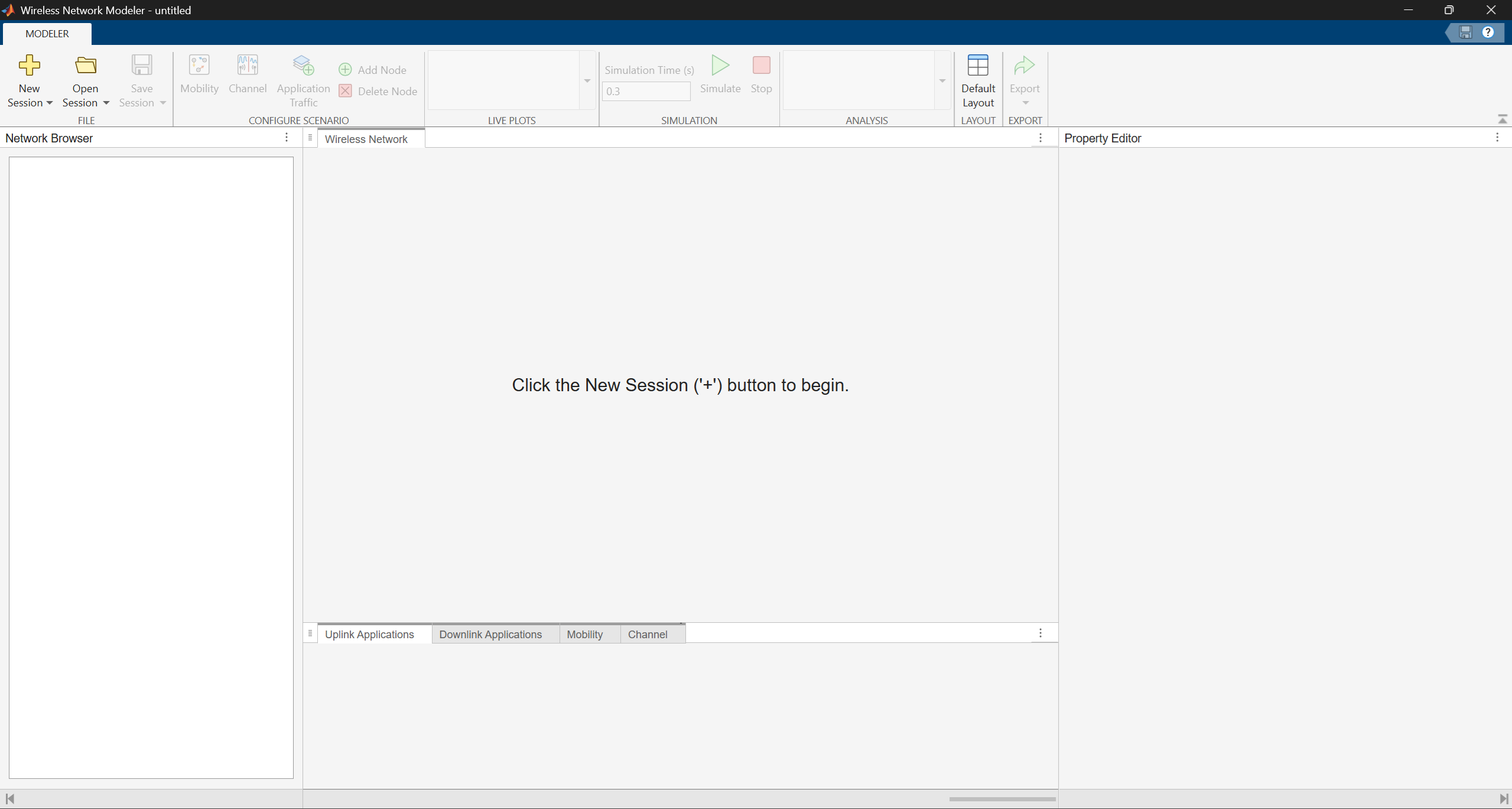
Open the Wireless Network Modeler app.
On the app toolstrip, click New Session and select 5G Network.
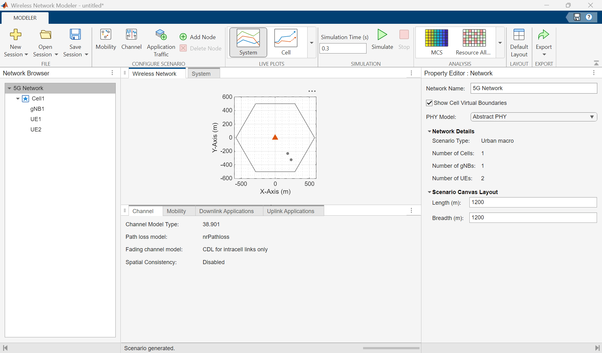
In the New 5G Network dialog box, set Scenario Type to
Urban macro.In the Nodes Placement section, set Number of gNBs to
1, UE Placement toEach cell, Number of UEs to2, Indoor UE Percentage to50, and Inter-Site Distance (m) to1200meters.Clear Enable full buffer application data traffic.
Click Create Network.
Configure NR Nodes
Configure the gNB and UE nodes by following these steps.
In the Property Editor: Network pane, set PHY Model to
Abstract PHY.In the Network Browser pane, select gNB1. In the Property Editor: Node pane for gNB1, in the Node Configuration section, set Number of Transmit Antennas to 16, Number of Receive Antennas to 16, and Transmit Power (dBm) to 35.
Click Apply.
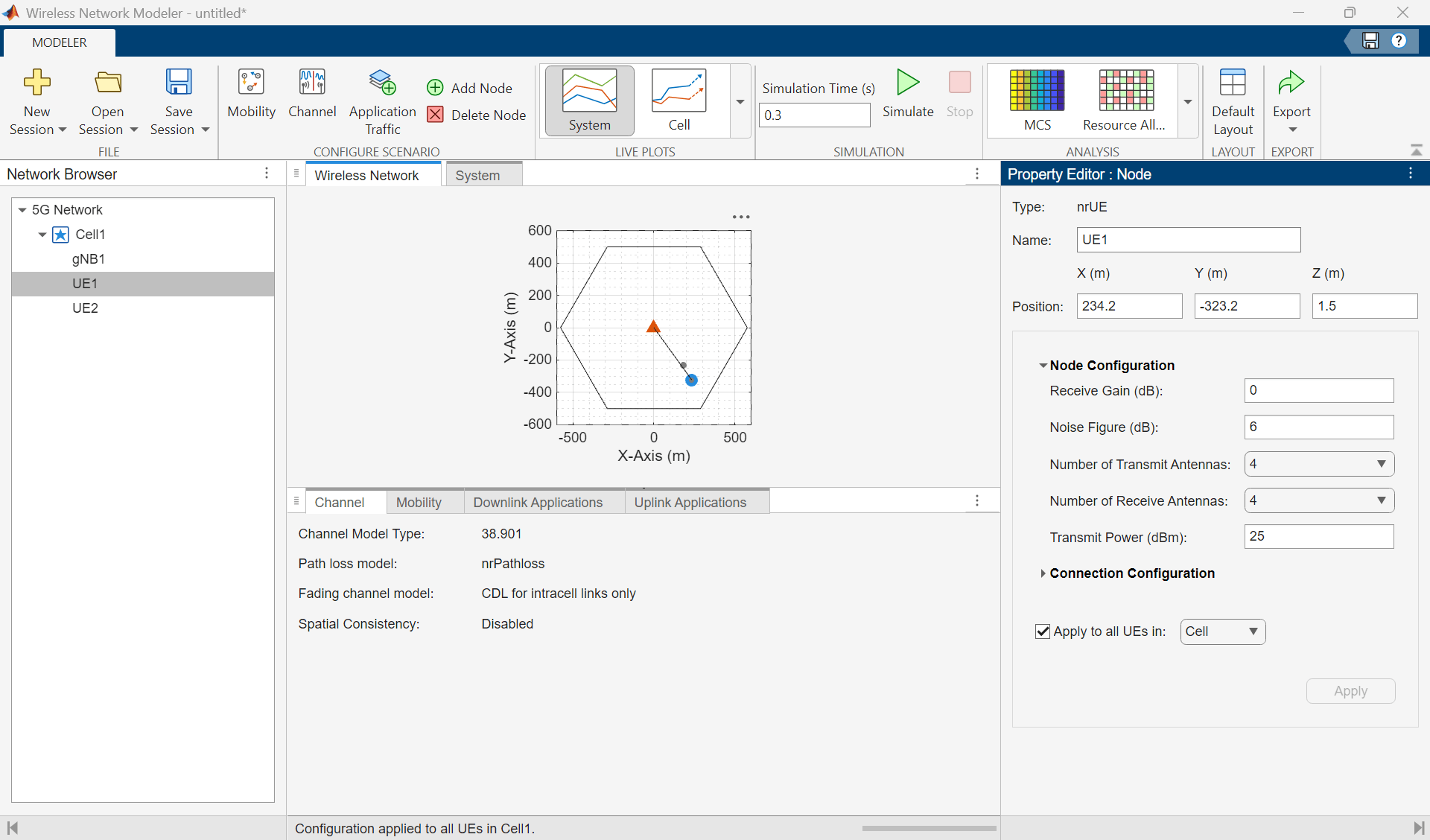
In the Network Browser pane, select UE1. In the Property Editor: Node pane for UE1, in the Node Configuration section, set Number of Transmit Antennas to 4, Number of Receive Antennas to 4, and Transmit Power to 25.
Select Apply to all UEs in, set it to
Cell, and then click Apply.
Add Mobility to UE Nodes
Add a mobility model to the UE nodes by following these steps.
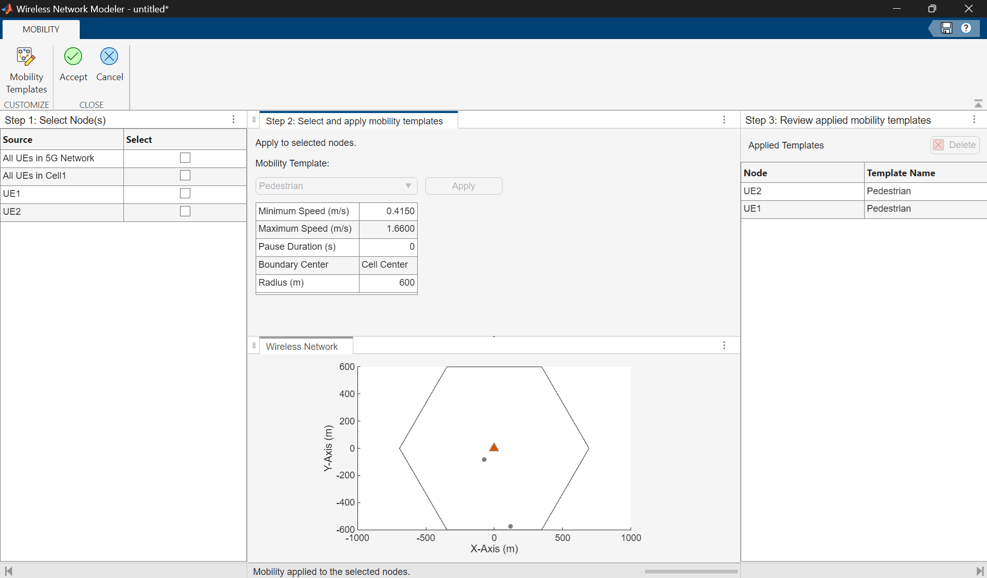
In the Configure Scenario section of the toolstrip, select Mobility.
In the table in the Select Nodes pane, select All UEs in 5G Network.
In the Select and apply mobility templates pane, click Apply.
On the toolstrip, click Accept.
Configure Custom Channel
Configure a custom channel by following these steps:
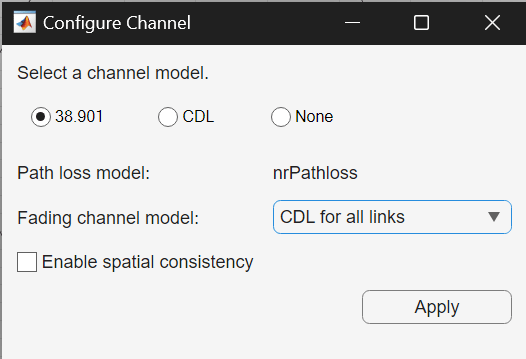
In the Configure Scenario section of the toolstrip, select Channel.
In the Configure Channel dialog box, set Select a Channel Model to
38.901. Set Fading channel model toCDL for all links.Click Apply.
Configure RLC Bearer Between gNB and Each UE Node
Establish a radio link control (RLC) bearer between the gNB and each UE node by following these steps:
In the Configure Scenario section of the toolstrip, select Application Traffic.
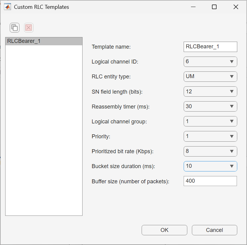
In the Customize section of the toolstrip, select RLC Templates.
In the Custom RLC Templates dialog box, set Bucket Size Duration (ms) to 10.
Add Application Traffic
In the Customize section of the app toolstrip, click Application Templates.
In the Custom Application Templates dialog box, in the left pane, select On-Off traffic and click to create a custom On-Off traffic template.
For the custom On-Off traffic template, specify Data Rate (Kbps) as
4+e04.In the Select uplink node pair(s) pane, select All UEs in the 5G Network. In the Select and apply templates pane, set Application Template to
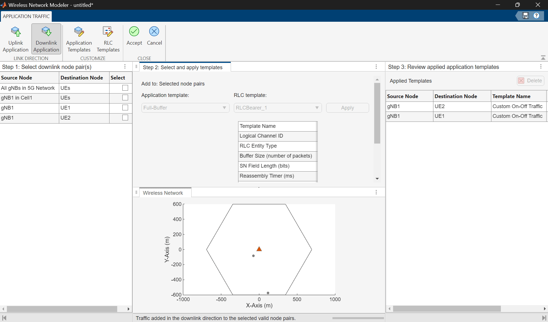
Custom_OnOff_1and RLC Template to RLC_Bearer_1, and click Apply.In the Select downlink node pair(s) pane, select All gNBs in the 5G Network. In the Select and apply templates pane, set Application Template to
Custom_OnOff_1and RLC Template to RLC_Bearer_1, and click Apply.On the toolstrip, click Accept.
Simulate and Analyze Network Performance
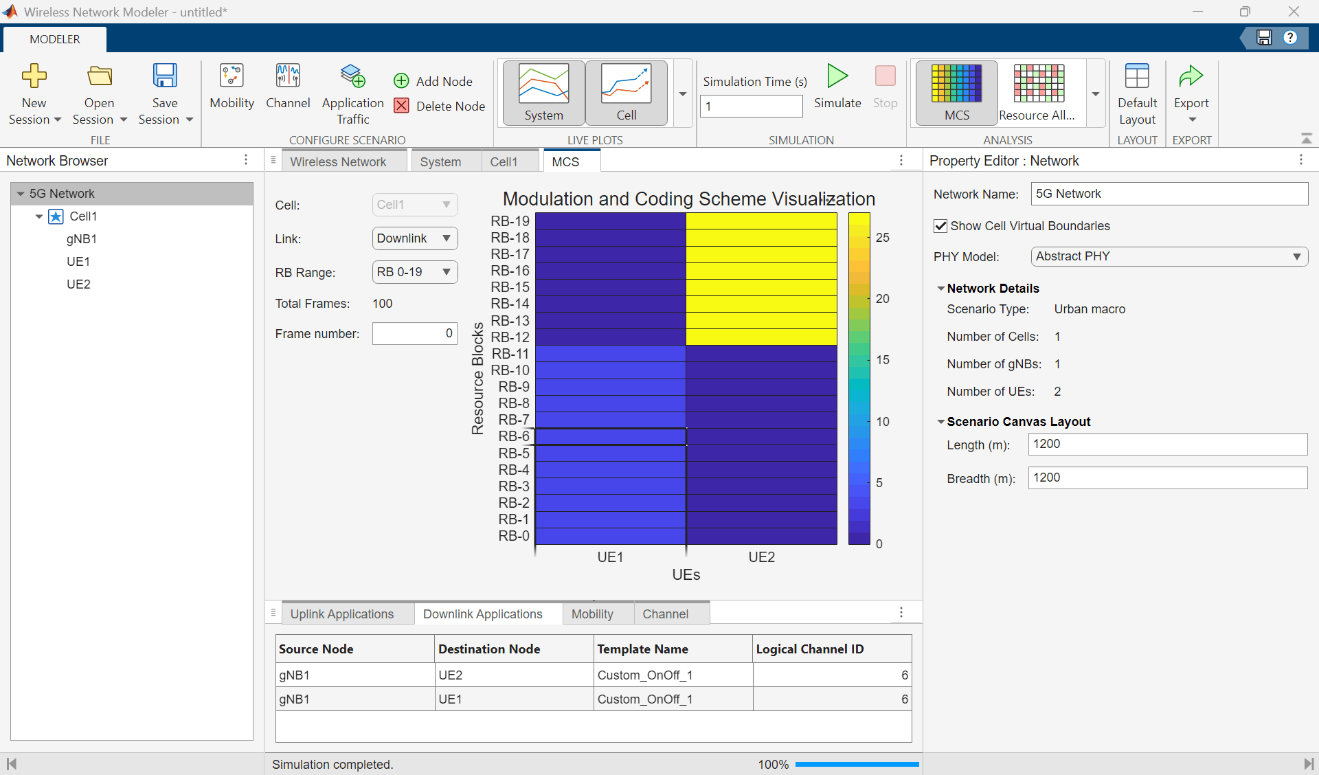
To analyze the cell-level performance (uplink throughput, downlink throughput, uplink block error rate (BLER), and downlink BLER), go to the app toolstrip. In the Live Plots section, select Cell. Then, in the Simulation section, click Simulate. You can monitor progress using the status bar at the bottom of the window.
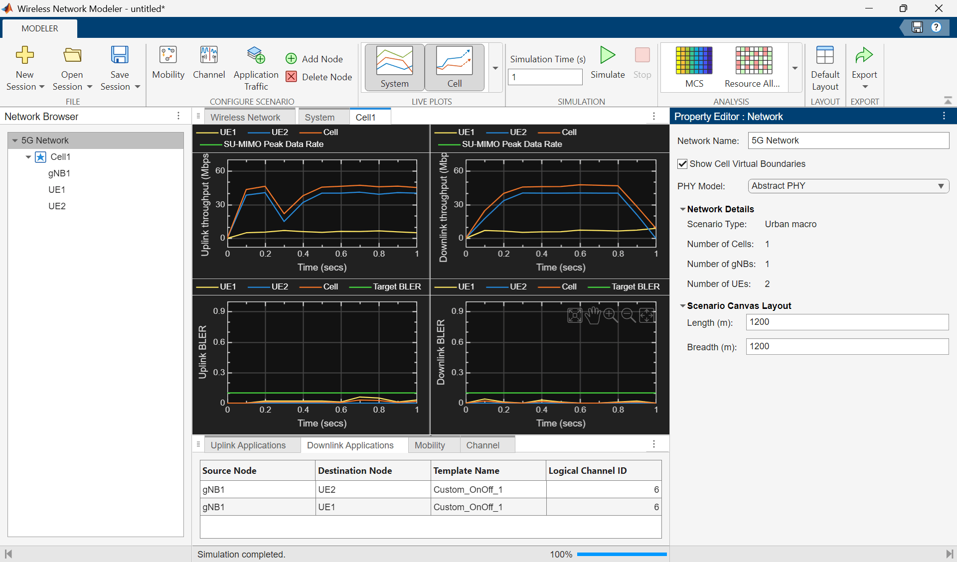
You can also visualize the modulation and coding scheme (MCS) for UE nodes and the resource allocation by selecting MCS and Resource Allocation in the Analysis section, respectively.
Further Exploration
Try exporting the MATLAB code or, alternatively, export results, logs, and visualizations for your 5G network scenario by clicking Export on the toolstrip and selecting either Export MATLAB script or Export Results and Logs. You can also save the session to a MAT file and load it back to continue in a later session.
Model a wireless local area network (WLAN), consisting of an access point (AP) and two stations (STAs), using the Wireless Network Modeler app.
Create WLAN Network
Follow these steps to create a WLAN network using the Wireless Network Modeler app.
Open the Wireless Network Modeler app.
On the app toolstrip, click New Session and select WLAN Network.
In the Nodes Placement section, set Number of AP to
1and Number of STA per AP to2.Clear Enable full buffer application data traffic.
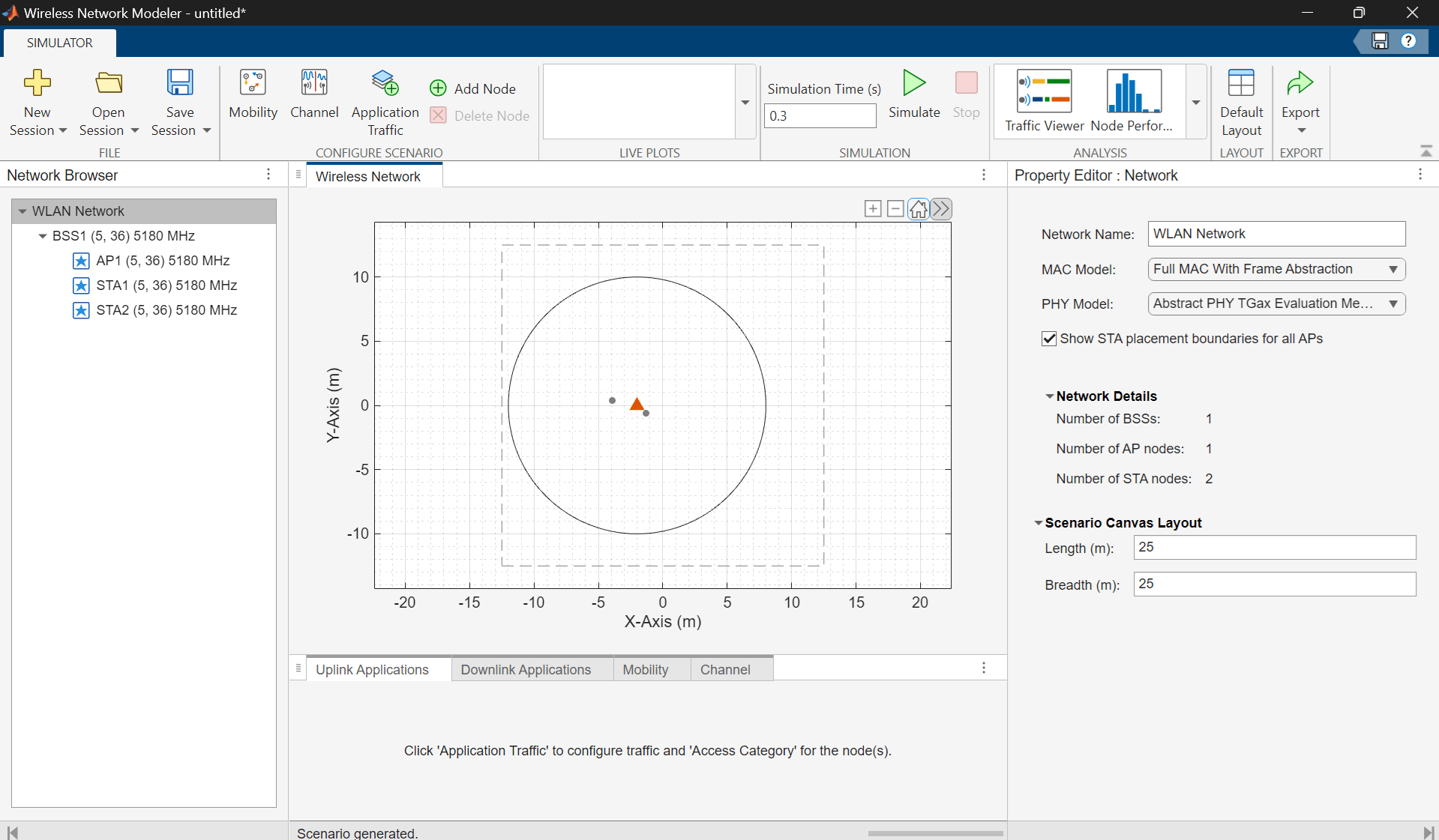
Click Create Network.
Configure WLAN Nodes
Configure the WLAN nodes by following these steps.
In the Property Editor: Network pane, you can set PHY Model and MAC Model. This example retains their default values.
In the Network Browser pane, select AP1. In the Property Editor: Node pane for AP1, in the Node Configuration section, set Modulation and coding scheme to
2, Number of transmit antennas to2, Number of space-time streams to2, and Transmit power to15.Click Apply.
In the Network Browser pane, select STA1. In the Property Editor: Node pane for STA1, in the Node Configuration section, set Modulation and coding scheme to
2, Number of transmit antennas to2, Number of space-time streams to2, and Transmit power to15.Click Apply.
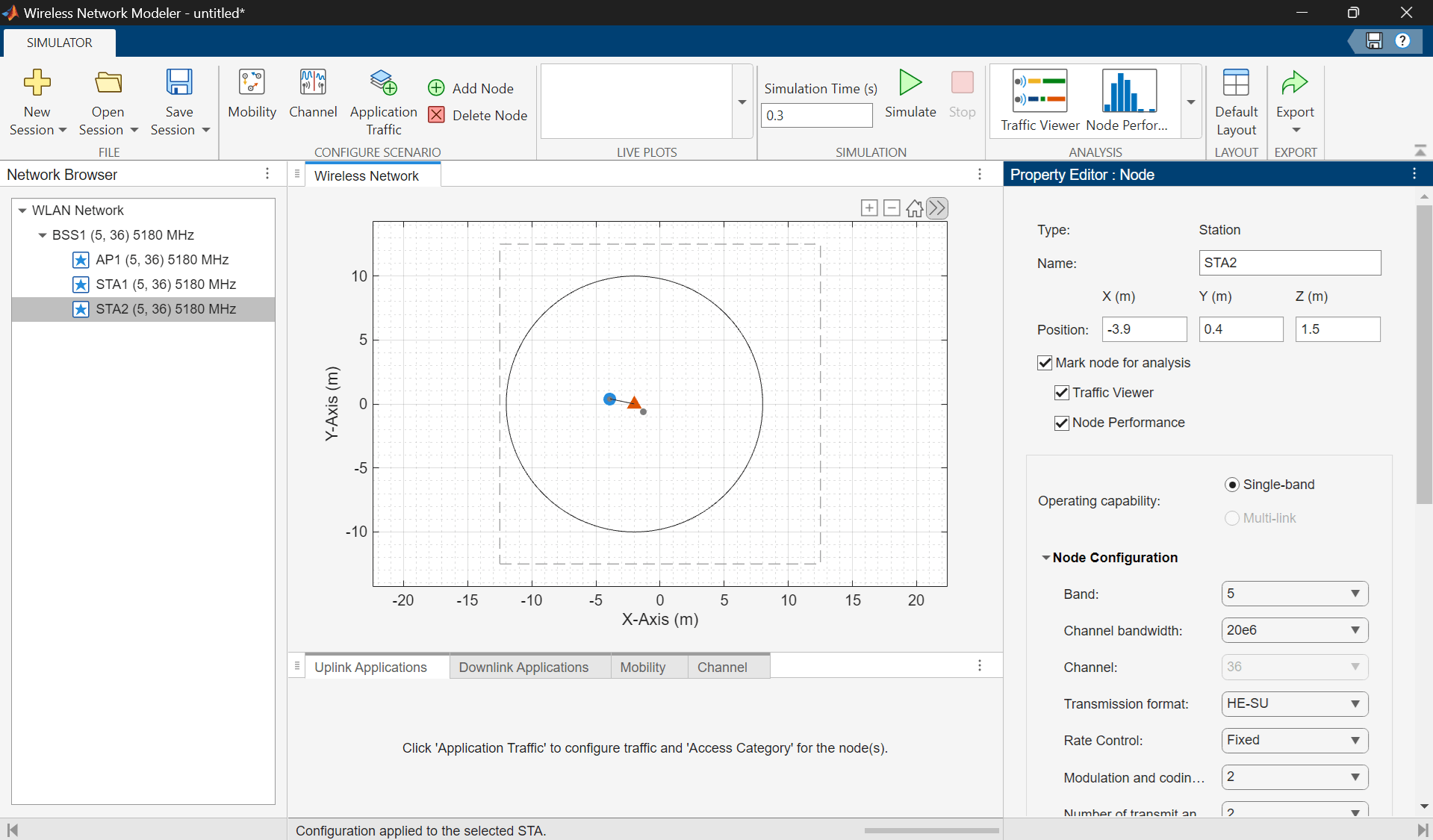
In the Network Browser pane, select STA2 and configure it with the same parameter values as STA1. Then, click Apply.
Add Mobility to Station Nodes
Add a mobility model to the station nodes by following these steps.
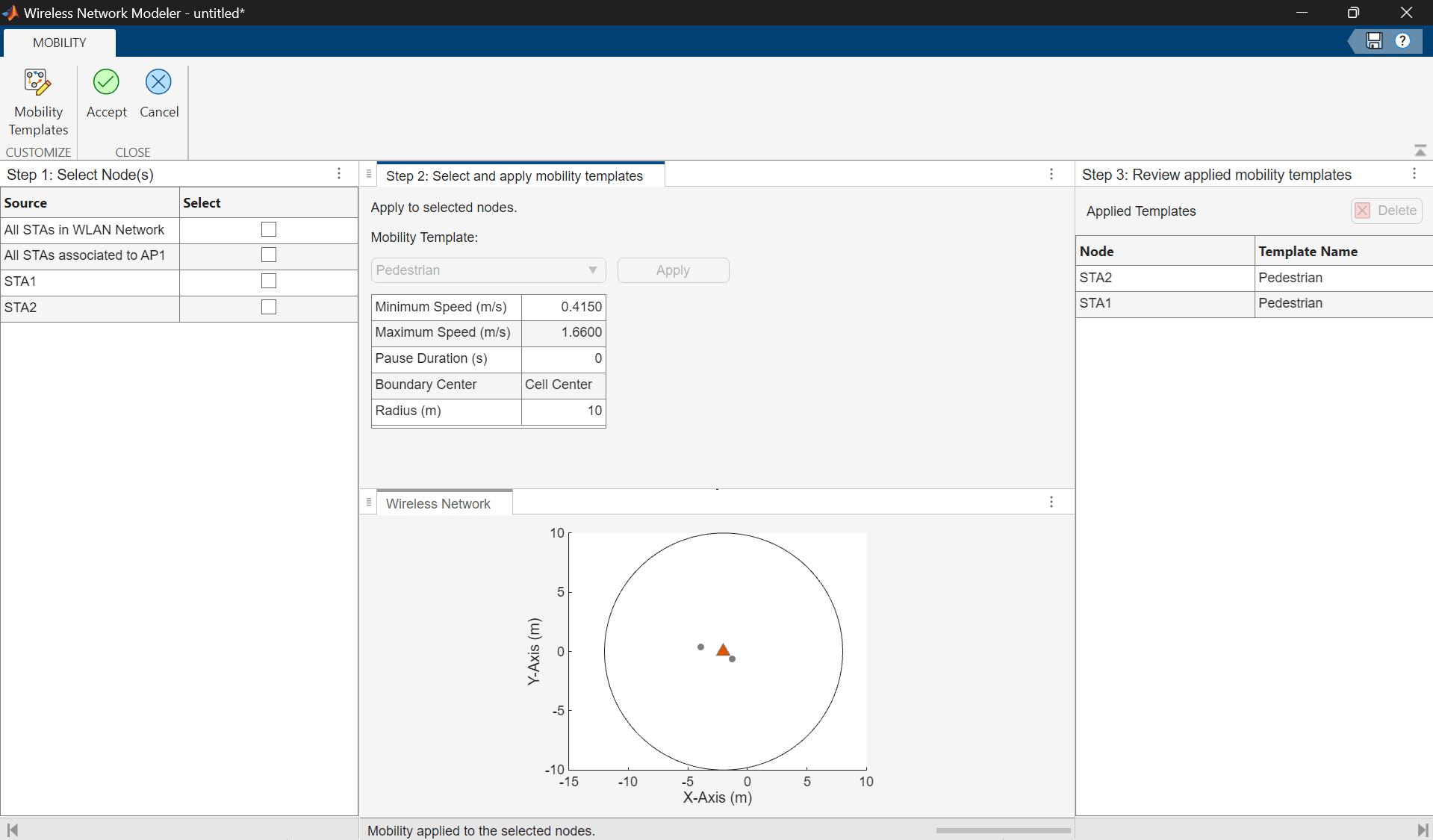
In the Configure Scenario section of the toolstrip, select Mobility.
In the table in the Select Nodes pane, select All STAs in WLAN Network.
In the Select and apply mobility templates pane, click Apply.
On the toolstrip, click Accept.
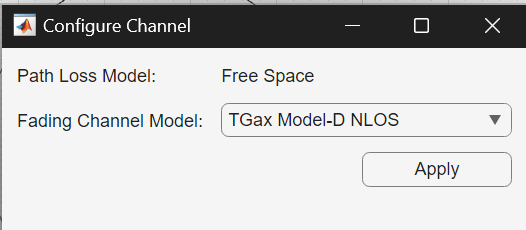
Configure Channel
In the Configure Scenario section of the toolstrip, select Channel. Then, in the Configure Channel dialog box, set Fading Channel Model to TGax Model-D NLOS, and click Apply.
Configure Application Traffic
To configure the application traffic, follow these steps.
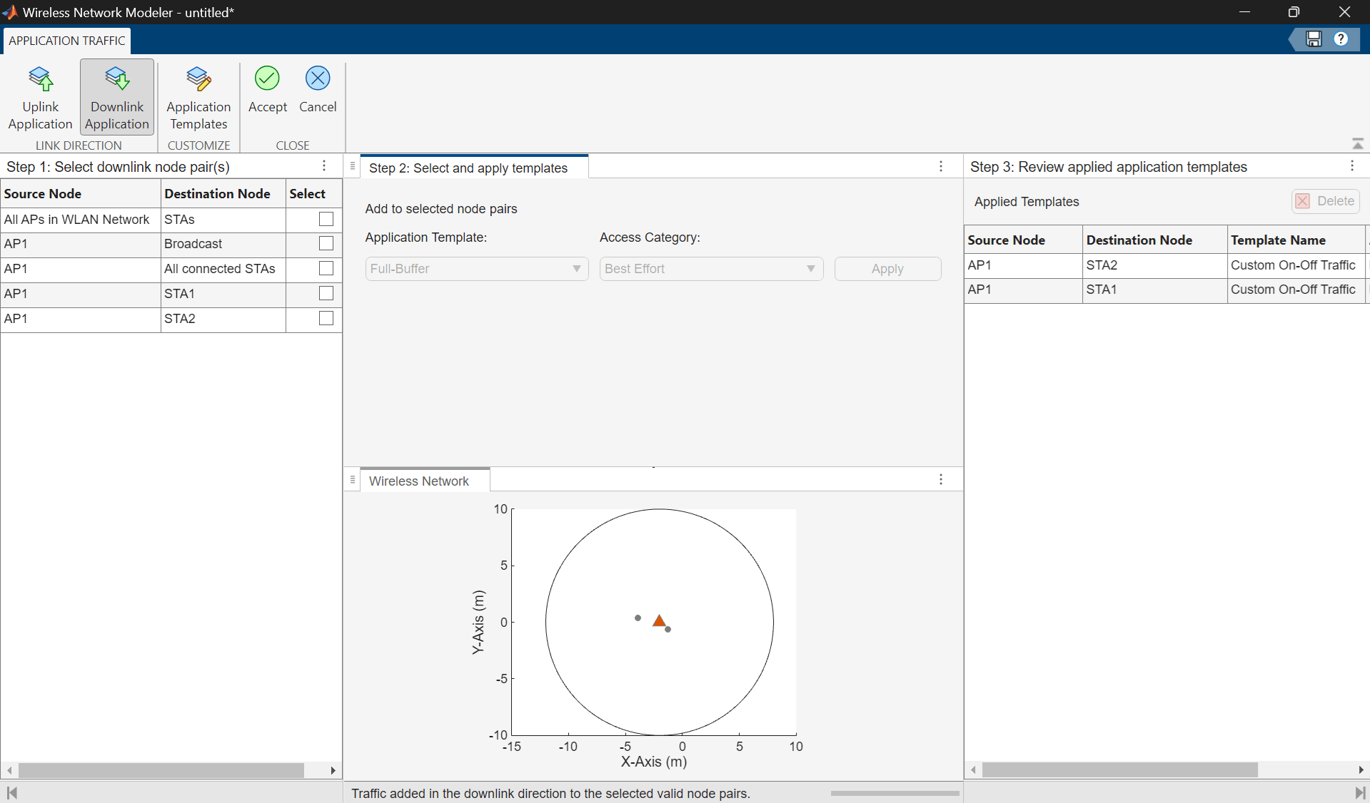
Add Application Traffic
In the Configure Scenario section of the toolstrip, select Application Traffic.
In the Customize section of the app toolstrip, click Application Templates.
In the Custom Application Templates dialog box, in the left pane, select On-Off traffic and click to create a copy of the selected application template..
For the custom On-Off template, specify Template Name as
Custom Network On-Off.In the Select uplink node pair(s) pane, select All STAs in the WLAN Network. In the Select and apply templates pane, set Application Template to
Custom Network On-Offand Access Category toBest Effort, and click Apply.In the Select downlink node pair(s) pane, select All APs in the WLAN Network. In the Select and apply templates pane, set Application Template to
Custom Network On-Offand Access Category toBest Effort, and click Apply.On the toolstrip, click Accept.
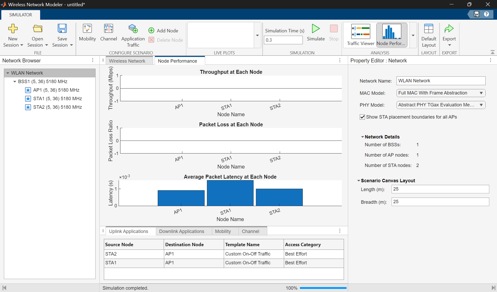
Simulate and Analyze Network Performance
On the app toolstrip, click Simulate in the Simulation section. To analyze the throughput, latency, and packet loss of the nodes, click Node Performance in the Analysis section. You can monitor progress using the status bar at the bottom of the window. This displays the Node Performance pane.
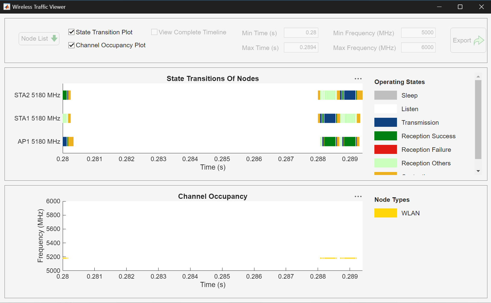
To view the state transitions and channel occupancy of the WLAN nodes, click Traffic Viewer in the Analysis section. The Wireless Traffic Viewer window provides a visual summary of how each node transitions between the contend, transmit, receive, listen, and sleep states.
Further Exploration
Try exporting the MATLAB code or, alternatively, export results, logs, and visualizations for your WLAN network scenario by clicking Export on the toolstrip and selecting either Export MATLAB script or Export Results and Logs. You can also save the session to a MAT file and load it back to continue in a later session.
Related Examples
Limitations
With respect to 5G network simulation, the Wireless Network Modeler app does not support these functionalities:
Channel state information (CSI) report configuration.
Sounding reference signal (SRS) based downlink subband measurements.
Custom scheduler configurability.
Providing UE-specific context to the scheduler.
Cell sectorization.
Cumulative distribution function (CDF) plot for cell throughput and average BLER.
Configurability of certain aspects of the 38.901 system-level channel model and 3GPP scenario configurations.
More than a limited number of gNBs (only 1, 7, and 19 are supported), with toroidal wrap-around available only for 19 gNBs.
With respect to WLAN network simulation, the app does not support these functionalities:
Station-to-station traffic.
Residential and mesh network scenarios.
Custom rate control algorithm configurability.
With respect to both 5G and WLAN, the app does not support these functionalities:
Node mobility within rectangular boundaries.
Random walk and constant velocity mobility models. Currently, the app supports only random waypoint mobility model with these configuration options: speed range, pause duration, and radius.
Packet capture (PCAP) logging, in-phase and quadrature (IQ) logging, and event logging.
File transfer protocol (FTP) traffic configurability.
Heterogeneous networks.
Version History
Introduced in R2026a
See Also
Objects
wirelessNetworkSimulator|nrGNB(5G Toolbox) |nrUE(5G Toolbox) |wlanNode(WLAN Toolbox)