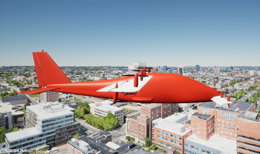
Custom Vertical Takeoff and Landing Example
This example highlights custom aircraft visualization capabilities by showing four example flights to destinations in the city of Boston. Visualization is provided by Cesium for Unreal®, with photorealistic 3D tiles from the Google Maps® platform. The vertical takeoff and landing (VTOL) locations are described by their latitude, longitude, and altitude (relative to WGS84). Each flight uses the custom aircraft mesh, each configured differently to illustrate possibilities available with the provided mesh.
The aircraft skeleton type is Custom. It has 57 bones, as shown in the following table.
The translation and rotation structure signals.values field indexes these bones from 1 to 57. Custom aircraft mesh bones are oriented with their primary axis vertical, except for rotating meshes. Engine and propeller bones face forward, and wheel bones face to the right. The bone y-axis is primary.
Set Up the Example
To create the variables used by the Simulink® model CustomVTOLExample.slx:
Start MATLAB® with administrative privileges.
Run this live script. Translation and rotation structures are created for the From Workspace blocks in the model.
In the model, customize the Simulation 3D Scene Configuration block with your Cesium Ion® token. For more information, see "Visualize with Cesium".
Boston Tour Mission
The mission is to make four flights to destinations in the city of Boston. The aircraft latitude, longitude, and altitude describe the takeoff and landing locations.
npts = 5;  % number of flights plus one
takeoffpts = zeros(npts, 3);
takeoffpts(1,:) = [42.329545, -71.049227, -24.80];  % Thomas Viens Little League fields
takeoffpts(2,:) = [42.343470, -71.049331, -23.50];  % Boston Convention & Exhibit Center
takeoffpts(3,:) = [42.333805, -71.071351, -24.20];  % Boston City Hospital helipad
takeoffpts(4,:) = [42.354255, -71.067202, -23.35];  % Boston Common baseball diamond
takeoffpts(5,:) = [42.371606, -71.057163, -25.90];  % USS Constitution Wharf
Latitude and longitude values can be found from a mapping application. The altitude is the height above the WGS84 ellipsoid model of the Earth at the given latitude and longitude. Experimentally find the altitude by first using a value that places the aircraft above ground. Run the model. Note the altitude sensor reading at that takeoff or landing point. Then correct the altitude value above by subtracting the altitude sensor reading from it to place the aircraft on the terrain.
Determining the flight time between these locations requires the distance. The distance between latitude and longitude pairs can be found in various ways. This example uses the geoTrajectory object in the helper function latlondist. The true course (i.e., azimuth) angle between takeoff and landing locations is obtained at the same time.
ac.Distance = zeros(1, npts-1);
ac.Course = zeros(1, npts-1);
for i = 1:npts-1
    [ac.Distance(i), ac.Course(i)] = latlondist(takeoffpts(i,1), ...
        takeoffpts(i,2), takeoffpts(i+1,1), takeoffpts(i+1,2));
end
Conditions
Set up the time conditions of the flight.
The performance of the aircraft impacts the flight time. Set the desired flight speed, rate of climb, acceleration, and cruising altitude. The rate of climb is used as the rate of descent as well. The International System of Units (SI) are used throughout this example.
ac.FlightAlt = 100;
ac.RateOfClimb = 10;
ac.FlightSpeed = 103;
ac.Accel = 10;
To reorient and reconfigure in between flights requires a setup time that must be five seconds or greater.
These events happen during this time:
Transition from takeoff to cruise mode.
Reconfiguration and reorientation to the new course.
Transition back to takeoff mode.
To allow adequate time for reconfiguring and reorientation, the time spent by the two mode transitions, 2*act.Trans, must be less than act.Config.
act.Config = 6;
act.Trans = 2;
if act.Config < 5
    act.Config = 5;
end
if act.Config-2*act.Trans < 1
    act.Config = 2*act.Trans + 1;
end
Calculate the total mission time. The local function, flighttimes, returns both the total and the segment times.
[act.Total, act.Segments] = flighttimes(ac.Distance, act.Config, ...
    ac.FlightAlt, ac.RateOfClimb, ac.FlightSpeed, ac.Accel);
Create convenient segment indices for each of the four flights.
j = 0:npts-2;
isegment.Config = [1 + 6*j, length(act.Segments)];
isegment.Takeoff = 2 + 6*j;
isegment.Accel =   3 + 6*j;
isegment.Land =    6 + 6*j;
Create a running total time.
act.Running = zeros(1, length(act.Segments));
for i = 2:length(act.Segments)
    act.Running(i) = act.Running(i-1) + act.Segments(i-1);
end
Initialization
Initialize the translation and rotation structures with time for the From Workspace blocks. Use a fixed time step of one-tenth of a second.
nseconds = floor(act.Total);
fprintf('The model run time is %d seconds.\n', nseconds)
The model run time is 229 seconds.
samplerate = 0.1;
nsteps = 1 + floor(nseconds/samplerate);
translation.time = samplerate*double(0:(nsteps-1));
translation.time = translation.time';
rotation.time = translation.time;
Custom aircraft dimensions are as follows:
nrows = 57;
ncols = 3;
translation.signals.dimensions = [nrows ncols];
rotation.signals.dimensions = [nrows ncols];
Initialize translations and rotations to zero for all of the bones and time steps.
translation.signals.values = zeros(nrows, ncols, nsteps);
rotation.signals.values = zeros(nrows, ncols, nsteps);
As the flight progresses, the example adjusts the altitude. The model sets the origin to the latitude, longitude, and height of the first takeoff point.
Clean up temporary variables.
clear i j samplerate nrows ncols npts
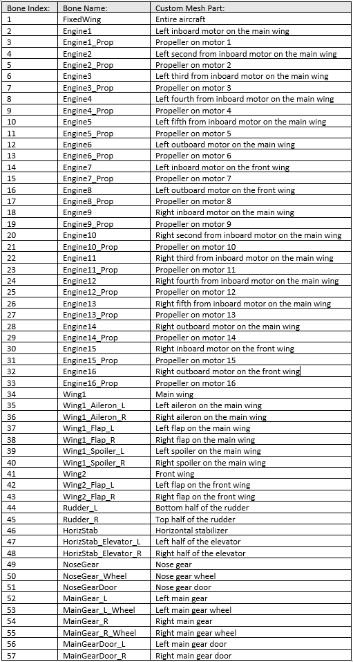
First Flight Configuration: Wings Rotate for Takeoff and Landing
For the first flight, the example uses the default aircraft configuration. During the last two seconds of the initial configuration time, to prepare for vertical takeoff, the example rotates the two wings to vertical.
icfg = 1;     % configuration and flight index, [1:4]
is1 = isegment.Takeoff(icfg);   % trunning(is1) is time at start of takeoff
tfinal = act.Running(isegment.Config(icfg+1)) + act.Segments(is1);  % time at end of config after landing
[translation, rotation] = acsetup(1, icfg, act.Running(is1)-act.Trans, ...
    act.Trans, tfinal, 90-ac.Course(icfg), translation, rotation);  % use UE heading
is2 = isegment.Accel(icfg);  % trunning(is2) is time at end of takeoff
[translation, rotation] = acconfig(icfg, act.Running(is1)-act.Trans, ...
    act.Trans, act.Running(is2), "takeoff", translation, rotation);  % hold through ascent
To take off, spin the propellers and ascend to cruise altitude.
[translation, rotation] = actakeoff(icfg, act.Running(is1), ...
    act.Running(is2), ac.FlightAlt, translation, rotation);
The cruise portion of the flight begins with an acceleration to cruise speed, the first portion of which includes a transition from vertical to horizontal thrust configuration. Similarly, the last portion of the cruise includes a transition back to vertical thrust.
is1 = is2;  % trunning(is1) is time at start of acceleration to cruise
is2 = isegment.Land(icfg);  % trunning(is2) is time at end of deceleration from cruise
tmodetrans = min(6, act.Segments(is1));  % transition between vertical and horizontal flight modes
[translation, rotation] = accruise(icfg, act.Running(is1:is2+1), ...
    tmodetrans, ac.FlightSpeed, ac.Course(icfg), translation, rotation);
Note: The transition to and from vertical and horizontal (wing-supported) flight is not modeled realistically. The purpose of this example is to illustrate the visualization capabilities of the Custom aircraft type, not to show VTOL aircraft dynamics.
The descent is the reverse of the ascent.
is1 = is2;  % trunning(is1) is time at start of landing
is2 = isegment.Config(icfg+1);  % trunning(is2) is time at end of landing
hdescent = takeoffpts(icfg+1, 3) - ac.FlightAlt - takeoffpts(icfg, 3);  % negative
[translation, rotation] = actakeoff(icfg, act.Running(is1), ...
    act.Running(is2), hdescent, translation, rotation);
Finish the first flight by returning the aircraft to its default mode, where the propellers all face forward.
is1 = is2;  % trunning(is1) is time at start of config after landing
[translation, rotation] = acconfig(icfg, act.Running(is1), ...
    act.Trans, tfinal, "cruise", translation, rotation);
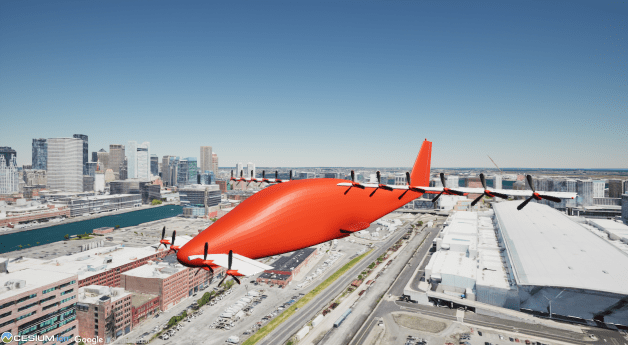
Second Flight Configuration: Motor Pods Rotate for Takeoff and Landing
For the second flight configuration, only the motor pods rotate to vertical for takeoff and landing. Both the main and the front wing stay fixed. However, their flaps are deployed to assist in vertical flight.
Otherwise, the steps are the same as for the first flight. The reconfiguration happens in the middle of the grounded time.
icfg = 2;  % configuration and flight #2
is1 = isegment.Config(icfg);  % trunning(is1) is time at start of this tconfig period
tfinal = act.Running(isegment.Config(icfg+1)) + act.Segments(is1);  % time at end of config after landing
[translation, rotation] = acsetup(icfg-1, icfg, act.Running(is1)+act.Trans, ...
    act.Config-2*act.Trans, tfinal, 90-ac.Course(icfg), translation, rotation);  % UE heading
is1 = isegment.Takeoff(icfg);
is2 = isegment.Accel(icfg);  % trunning(is2) is time at end of takeoff
[translation, rotation] = acconfig(icfg, act.Running(is1)-act.Trans, ...
    act.Trans, act.Running(is2), "takeoff", translation, rotation);  % hold through ascent
Takeoff.
[translation, rotation] = actakeoff(icfg, act.Running(is1), ...
    act.Running(is2), ac.FlightAlt, translation, rotation);
Cruise.
is1 = is2;  % trunning(is1) is time at start of acceleration to cruise
is2 = isegment.Land(icfg);  % trunning(is2) is time at end of deceleration from cruise
tmodetrans = min(6, act.Segments(is1));  % transition between vertical and horizontal flight modes
[translation, rotation] = accruise(icfg, act.Running(is1:is2+1), ...
    tmodetrans, ac.FlightSpeed, ac.Course(icfg), translation, rotation);
Descend to land.
is1 = is2;  % trunning(is1) is time at start of landing
is2 = isegment.Config(icfg+1);  % trunning(is2) is time at end of landing
hdescent = takeoffpts(icfg+1, 3) - ac.FlightAlt - takeoffpts(icfg, 3);  % negative
[translation, rotation] = actakeoff(icfg, act.Running(is1), ...
    act.Running(is2), hdescent, translation, rotation);
Reconfigure.
is1 = is2;  % trunning(is1) is time at start of config after landing
[translation, rotation] = acconfig(icfg, act.Running(is1), act.Trans, tfinal, "cruise", ...
    translation, rotation);
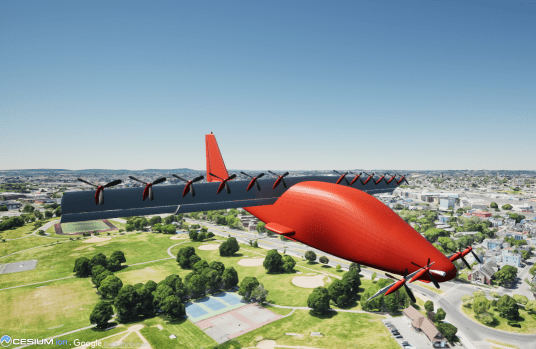
Third Flight Configuration: Motor Pods Rotate for Takeoff and Landing with Six Pusher Props
For the third flight configuration, move half of the main wing motors behind the wing to act as pushers. As with the second configuration, only the motor pods rotate to vertical for takeoff and landing.
icfg = 3;  % configuration and flight #3
is1 = isegment.Config(icfg);  % trunning(is1) is time at start of this tconfig period
tfinal = act.Running(isegment.Config(icfg+1)) + act.Segments(is1);  % time at end of config after landing
[translation, rotation] = acsetup(icfg-1, icfg, act.Running(is1)+act.Trans, ...
    act.Config-2*act.Trans, tfinal, 90-ac.Course(icfg), translation, rotation);  % UE heading
is1 = isegment.Takeoff(icfg);
is2 = isegment.Accel(icfg);  % trunning(is2) is time at end of takeoff
[translation, rotation] = acconfig(icfg, act.Running(is1)-act.Trans, ...
    act.Trans, act.Running(is2), "takeoff", translation, rotation);  % hold through ascent
Takeoff.
[translation, rotation] = actakeoff(icfg, act.Running(is1), ...
    act.Running(is2), ac.FlightAlt, translation, rotation);
Cruise.
is1 = is2;  % trunning(is1) is time at start of acceleration to cruise
is2 = isegment.Land(icfg);  % trunning(is2) is time at end of deceleration from cruise
tmodetrans = min(6, act.Segments(is1));  % transition between vertical and horizontal flight modes
[translation, rotation] = accruise(icfg, act.Running(is1:is2+1), ...
    tmodetrans, ac.FlightSpeed, ac.Course(icfg), translation, rotation);
Descend to land.
is1 = is2;  % trunning(is1) is time at start of landing
is2 = isegment.Config(icfg+1);  % trunning(is2) is time at end of landing
hdescent = takeoffpts(icfg+1, 3) - ac.FlightAlt - takeoffpts(icfg, 3);  % negative
[translation, rotation] = actakeoff(icfg, act.Running(is1), ...
    act.Running(is2), hdescent, translation, rotation);
Reconfigure.
is1 = is2;  % trunning(is1) is time at start of config after landing
[translation, rotation] = acconfig(icfg, act.Running(is1), act.Trans, tfinal, "cruise", ...
    translation, rotation);
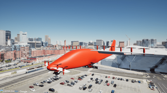
Fourth Flight Configuration: Front Wing and Main Wing Motor Pods Rotate for Takeoff and Landing with Two Fixed Cruise Motors

For the fourth flight configuration, move two of the wing motors to the horizontal stabilizer. They remain fixed in the forward-facing position. In this configuration, the main wing does not rotate to vertical, but the front wing does.
icfg = 4;  % configuration and flight #4
is1 = isegment.Config(icfg);  % trunning(is1) is time at start of this tconfig period
tfinal = translation.time(end);  % tfinal for last flight
[translation, rotation] = acsetup(icfg-1, icfg, act.Running(is1)+act.Trans, ...
    act.Config-2*act.Trans, tfinal, 90-ac.Course(icfg), translation, rotation);  % UE heading
is1 = isegment.Takeoff(icfg);
is2 = isegment.Accel(icfg);  % trunning(is2) is time at end of takeoff
[translation, rotation] = acconfig(icfg, act.Running(is1)-act.Trans, ...
    act.Trans, act.Running(is2), "takeoff", translation, rotation);  % hold through ascent
Takeoff.
[translation, rotation] = actakeoff(icfg, act.Running(is1), ...
    act.Running(is2), ac.FlightAlt, translation, rotation);
Cruise.
is1 = is2;  % trunning(is1) is time at start of acceleration to cruise
is2 = isegment.Land(icfg);  % trunning(is2) is time at end of deceleration from cruise
tmodetrans = min(6, act.Segments(is1));  % transition between vertical and horizontal flight modes
[translation, rotation] = accruise(icfg, act.Running(is1:is2+1), ...
    tmodetrans, ac.FlightSpeed, ac.Course(icfg), translation, rotation);
Descend to land.
is1 = is2;  % trunning(is1) is time at start of landing
is2 = isegment.Config(icfg+1);  % trunning(is2) is time at end of landing
hdescent = takeoffpts(icfg+1, 3) - ac.FlightAlt - takeoffpts(icfg, 3);  % negative
[translation, rotation] = actakeoff(icfg, act.Running(is1), ...
    act.Running(is2), hdescent, translation, rotation);
Reconfigure.
is1 = is2;  % trunning(is1) is time at start of config after landing
[translation, rotation] = acconfig(icfg, act.Running(is1), act.Trans, tfinal, "cruise", ...
    translation, rotation);
Clean up temporary variables.
clear isegment icfg is1 is2 hdescent tmodetrans tfinal
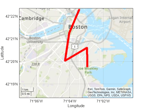
Plot Flight Tracks
To plot the flight ground tracks, use the flat2lla function to convert from the north-east-down (NED) coordinate frame to geodetic coordinates. Plot the latitude and longitude points on a topographic map. Note that the translation and rotation arrays for Unreal Engine® have the x-axis pointing East and the y-axis pointing South.
lat = zeros(nsteps, 1);
lon = zeros(nsteps, 1);
lat(1) = takeoffpts(1,1);
lon(1) = takeoffpts(1,2);
for i = 2:nsteps
    xNorth = -translation.signals.values(1, 2, i);
    yEast = translation.signals.values(1, 1, i);
    lla = flat2lla([xNorth, yEast, 0], [takeoffpts(1,1), takeoffpts(1,2)], 0, 0);
    lat(i) = lla(1);
    lon(i) = lla(2);
end

geobasemap topographic
geoplot(lat, lon, '*r')
[latlims, lonlims] = geolimits;
dlat = 0.5*(latlims(2) - latlims(1));
geolimits([latlims(1)-dlat, latlims(2)], [lonlims(1)-0.5*dlat, lonlims(2)+0.5*dlat])
Clean up temporary variables.
clear i xNorth yEast lat lon nsteps latlims lonlims dlat
Run
Now that the translation and rotation structures have been fully calculated, open the Simulink model and set the stop time.
open_system("CustomVTOLExample.slx");
set_param("CustomVTOLExample", "StopTime", num2str(nseconds));
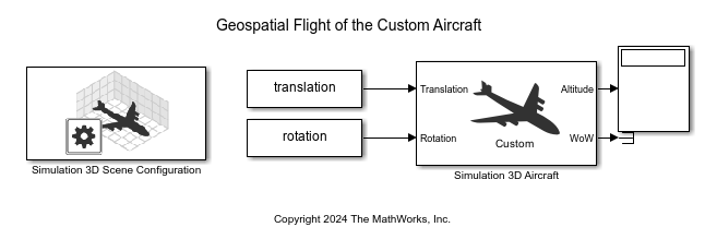
Select the Geospatial tab from the Simulation 3D Scene Configuration block mask and enter your Cesium access token ID. Press OK to save and close the dialog box. For more information, see the Visualize with Cesium documentation.
Click the Run button to view the flights.
If takeoff and landing locations or performance numbers are changed, rerun this live script.
Helper Functions
Besides the two helper functions below, this example uses eight other functions: acconfig, accruise, acldggear, acsetup, actakeoff, acwingflaps, geotransform, and timeindices.
function [distance, azimuth] = latlondist(lat1, lon1, lat2, lon2)
%LATLONDIST Calculate the distance and azimuth angle between a pair
%of locations, defined by their latitude and longitude.
%
% Use Sensor Fusion's "geoTrajectory" system object to make the
% calculations.
%
% Input Variables:
%   lat1, lon1 = starting location
%   lat2, lon2 = ending location
%
% Output Variables:
%   distance = distance in meters between starting and ending locations
%   azimuth = azimuth in degrees of ending location with respect to the
%             starting location

traveltime = [0 1];  % 1 second trajectory so velocity equals distance
samplerate = 0.5;      % 3 samples (doesn't affect accuracy)
trajectory = geoTrajectory([lat1 lon1, 0; lat2, lon2, 0], traveltime, ...
    'SampleRate', samplerate);

% Use lookupPose to get velocity (m/s) at end of trajectory
[~, ~, velocity, ~, ~, ~] = lookupPose(trajectory, 1);
distance = sqrt(velocity(1)^2 + velocity(2)^2);

% Get azimuth from the Course property
azimuth = trajectory.Course(end);
while azimuth < 0  % add 360 degrees if negative
    azimuth = 360 + azimuth;
end
end

function [ttotal, tsegments] = flighttimes(distances, tconfig, ...
    altitude, acroc, acspeed, acaccel)
%FLIGHTTIMES Calculate flight segment times.
% Find the time for each segment of a VTOL mission. VTOL flights have
% 1 + 6N segments for "N" total flights: configure, climb, accelerate,
% cruise, decelerate, descend, reconfigure, etc. Note that the wind is
% assumed to be calm.
%
% Input Variables:
%   distances = 1-by-N vector of flight distances (m)
%   tconfig = time before, between, and after each flight (s)
%   altitude = cruise altitude above the takeoff point (m)
%   acroc = aircraft rate of climb (m/s)
%   acspeed = aircraft cruise flight speed (m/s)
%   acaccel = aircraft rate of acceleration in level flight (m/s^2)
%
% Output Variables:
%   ttotal = total mission time (s)
%   tsegments = mission time for each segment (s)

N = length(distances);
tsegments = zeros(1, N);

is = 1;  % segment index
tsegments(is) = tconfig;
is = is + 1;
for i = 1:N
    tsegments(is) = altitude / acroc;
    is = is + 1;
    tsegments(is) = acspeed / acaccel;
    is = is + 1;
    % Get distance flown during acceleration and deceleration segments
    acdcdist = distances(i) - acspeed*tsegments(is-1);
    if acdcdist < 0
        error("Error: Zero time remaining for cruise segment!");
    end
    tsegments(is) = acdcdist / acspeed;
    is = is + 1;
    tsegments(is) = tsegments(is-2);  % deceleration = acceleration
    is = is + 1;
    tsegments(is) = tsegments(is-4);  % descent = climb
    is = is + 1;
    tsegments(is) = tconfig;
    is = is + 1;
end
ttotal = sum(tsegments);
end