Create and Configure AUTOSAR Software Component
Create an AUTOSAR software component model from an algorithm model.
AUTOSAR Blockset software supports AUTomotive Open System ARchitecture (AUTOSAR), an open and standardized automotive software architecture. Automobile manufacturers, suppliers, and tool developers jointly develop AUTOSAR components. To develop AUTOSAR components in Simulink, follow this general workflow:
Create a Simulink representation of an AUTOSAR component.
Develop the component by refining the AUTOSAR configuration and creating algorithmic model content.
Generate ARXML descriptions and algorithmic C code for testing in Simulink or integration into an AUTOSAR run-time environment. (AUTOSAR code generation requires Simulink Coder and Embedded Coder.)
Create AUTOSAR Software Component in Simulink
To create an initial Simulink representation of an AUTOSAR software component, you take one of these actions:
Create an AUTOSAR software component using an existing Simulink model.
Import an AUTOSAR software component description from ARXML files into a new Simulink model. (See example Import AUTOSAR Component to Simulink.)
To create an AUTOSAR software component using an existing model, first open a Simulink component model for which an AUTOSAR software component is not mapped. This example uses AUTOSAR example model swc.
open_system("swc");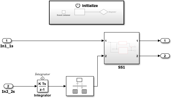
In the model window, on the Modeling tab, select Model Settings. In the Configuration Parameters dialog box, Code Generation pane, set the system target file to autosar.tlc. Click OK.
To configure the model as a mapped AUTOSAR software component, use the AUTOSAR Component Quick Start. On the Apps tab, click AUTOSAR Component Designer. The AUTOSAR Component Quick Start opens.
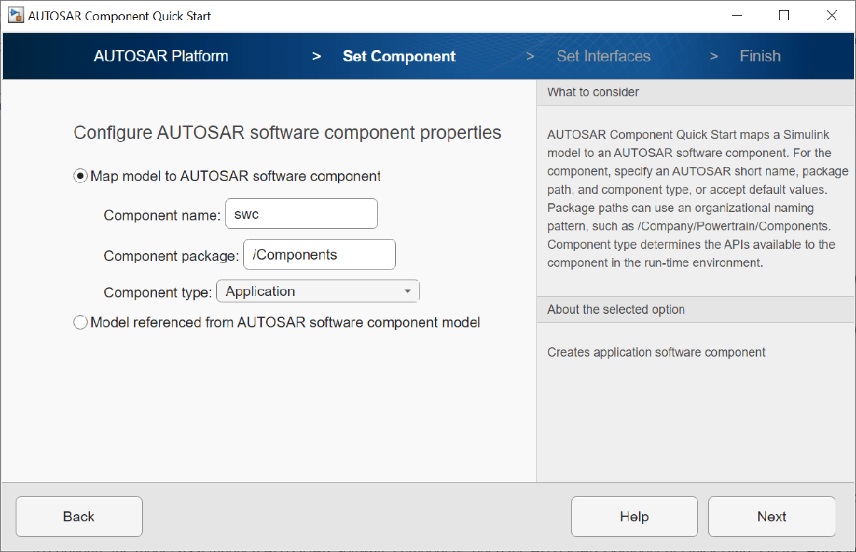
To configure the model for AUTOSAR software component development, work through the quick-start procedure. This example accepts default settings for the options in the Quick Start AUTOSAR Platform, Set Component, and Set Interfaces panes.
In the Finish pane, when you click Finish, your model opens in the AUTOSAR code perspective.
Configure AUTOSAR Software Component in Simulink
The AUTOSAR code perspective displays your model, and directly below the model, the Code Mappings editor.

Next you use the Code Mappings editor and the AUTOSAR Dictionary to further develop the AUTOSAR component.
The Code Mappings editor displays entry-point functions, model inports, outports, parameters, and other Simulink elements relevant to your AUTOSAR platform. Use the editor to map Simulink model elements to AUTOSAR component elements from a Simulink model perspective. AUTOSAR component elements are defined in the AUTOSAR standard, and include runnable entities, ports, and inter-runnable variables (IRVs).
Open each Code Mapping tab and examine the mapped model elements. To modify the AUTOSAR mapping for an element, select an element and modify its associated properties. When you select an element, it is highlighted in the model. To view additional code and communication attributes for the element, click the edit icon.
To configure the AUTOSAR properties of the mapped AUTOSAR software component, open the AUTOSAR Dictionary. In the Code Mappings editor, click the AUTOSAR Dictionary button, which is the leftmost icon. The AUTOSAR Dictionary opens in the AUTOSAR view that corresponds to the Simulink element that you last selected and mapped in the Code Mappings editor. If you selected and mapped a Simulink inport, the dictionary opens in ReceiverPorts view and displays the AUTOSAR port to which you mapped the inport.

The AUTOSAR Dictionary displays the mapped AUTOSAR component and its elements, communication interfaces, computation methods, software address methods, and XML options. Use the dictionary to configure AUTOSAR elements and properties from an AUTOSAR component perspective.
Open each node and examine its AUTOSAR elements. To modify an AUTOSAR element, select an element and modify its associated properties. AUTOSAR XML and AUTOSAR-compliant C code generated from the model reflect your modifications.
Generate C Code and ARXML Descriptions (Embedded Coder)
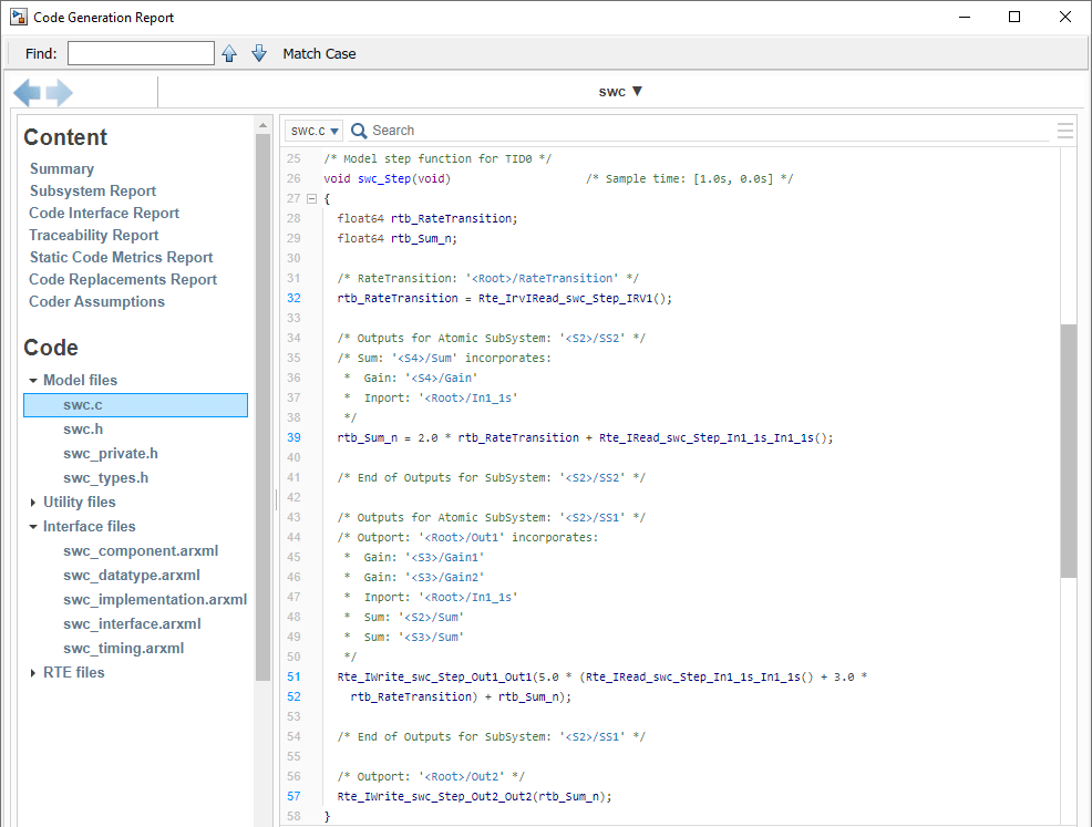
If you have Simulink Coder and Embedded Coder software, you can build the AUTOSAR model. Building the AUTOSAR model generates AUTOSAR-compliant C code and exports AUTOSAR XML (ARXML) descriptions. In the model window, press Ctrl+B or, on the AUTOSAR tab, click Generate Code.
When the build completes, a code generation report opens. Examine the report. Verify that your Code Mappings editor and AUTOSAR Dictionary changes are reflected in the C code and ARXML descriptions. For example, use the Find field to search for the names of the Simulink model elements and AUTOSAR component elements that you modified.
Related Links
Code Generation (Classic Platform)