Multiband Signal Generation
This example shows how to generate a multiband signal efficiently using the Communications Toolbox™.
Introduction
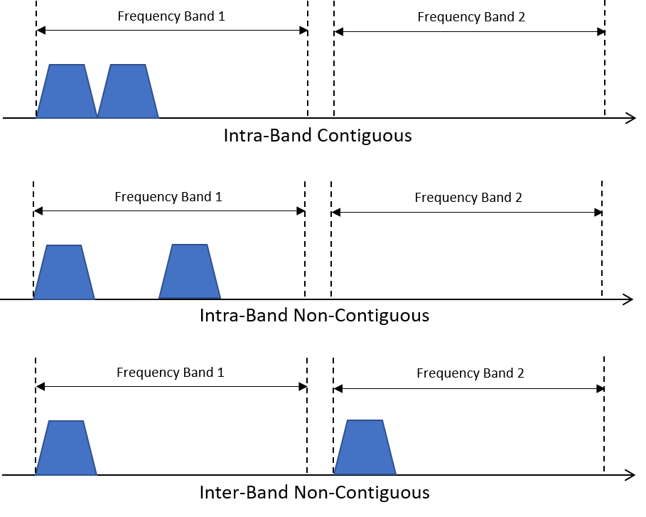
The explosive growth of consumer demand for higher data rates in mobile applications leads to higher transmission rates. Most modern wireless standards include a technique to enhance the data capacity by combining two or more carriers into one data channel. This technique is called carrier aggregation in 5G and LTE terminology, and channel bonding in Wi-Fi® terminology. This figure illustrates three different types of carrier aggregation.
System Setup
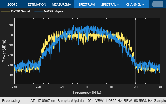
This example demonstrates one approach to model carrier aggregation in a baseband simulation. Two baseband signals are generated - one is a QPSK modulated signal and the other is a GMSK modulated signal. Each signal occupies 60 kHz of bandwidth.
A MultibandCombiner System object™ performs the tasks necessary for carrier aggregation. If the sample rate of the input signals is not high enough, the frequency content will be distorted when the original signals are frequency shifted to produce the desired carrier aggregation. Setting the OutputSampleRateSource property to "Auto" configures the object to automatically compute the output sample rate and interpolate the two signals if necessary to ensure that the resulting signal sample rate is high enough to avoid aliasing. The info method of the System object shows the sample rate of the output signal. After the interpolation, the object applies the specified frequency shifts to the signals and combines them into one signal. For more information about the algorithm processing, see the comm.MultibandCombiner reference page.
System Simulation
nFrames = 10; % Number of data frames
M = 4;        % Modulation order (QPSK modulation)
Fs1 = 60e3;   % Input sample rate

qpskTxFilter = comm.RaisedCosineTransmitFilter(RolloffFactor=0.3, ...
    OutputSamplesPerSymbol=2);

gmskMod = comm.GMSKModulator(BitInput=true,SamplesPerSymbol=2);
Create two multiband combiner objects One with specified frequency offsets for the intra-band contiguous aggregation and a second with specified frequency offsets for the intra-band noncontiguous aggregation.
sigCombinerCB = comm.MultibandCombiner( ...
    InputSampleRate=Fs1, ...
    FrequencyOffsets=[-30e3, 30e3], ...
    OutputSampleRateSource="Auto");
Fs2 = info(sigCombinerCB).OutputSampleRate;

sigCombinerNCB = comm.MultibandCombiner( ...
    InputSampleRate=Fs1, ...
    FrequencyOffsets=[-60e3, 60e3],OutputSampleRateSource="Auto");
Fs3 = info(sigCombinerNCB).OutputSampleRate;
Create individual spectrum analyzer scopes to display the baseband signals, the intra-band contiguous signal, and the intra-band noncontiguous signal.
scopeSF = 0.7; % Scale factor for scope position
spectrumBB = spectrumAnalyzer( ...
    Name="Baseband Signals", ...
    NumInputPorts=2, ...
    SampleRate=60e3, ...
    ShowLegend=true, ...
    ChannelNames={'QPSK Signal','GMSK Signal'});
spectrumBB.Position = scopeSF * spectrumBB.Position;
spectrumBB.Position(1) = spectrumBB.Position(1) - ...
    spectrumBB.Position(3);

spectrumCB = spectrumAnalyzer( ...
    Name="Intra-Band Contiguous", ...
    NumInputPorts=1, ...
    SampleRate=Fs2);
spectrumCB.Position = scopeSF * spectrumCB.Position;

spectrumNCB = spectrumAnalyzer( ...
    Name="Intra-Band Non-Contiguous", ...
    NumInputPorts=1, ...
    SampleRate=Fs3);
spectrumNCB.Position = scopeSF * spectrumNCB.Position;
spectrumNCB.Position(1) = spectrumNCB.Position(1) + ...
    spectrumNCB.Position(3);

for k = 1:nFrames

    % Generate QPSK signal
    data = randi([0, M-1],200,1);
    modSig = pskmod(data,M,pi/4,"gray");
    qpskSignal = qpskTxFilter(modSig);

    % Generate GMSK signal
    data = randi([0, 1],200,1);
    gmskSignal = gmskMod(data);

    % Visualize the two baseband signals
    spectrumBB(qpskSignal,gmskSignal)

    % Upsample, frequency shift and combine the two signals to model
    % intra-band contiguous carrier aggregation.
    combinedSignal = sigCombinerCB([qpskSignal,gmskSignal]);

    % Visualize the resulting signal
    spectrumCB(combinedSignal)

    % Upsample, frequency shift and combine the two signals to model
    % intra-band non contiguous or inter-band non contiguous carrier
    % aggregation.
    combinedSignal = sigCombinerNCB([qpskSignal,gmskSignal]);

    % Visualize the resulting signal
    spectrumNCB(combinedSignal)
end

Visualization
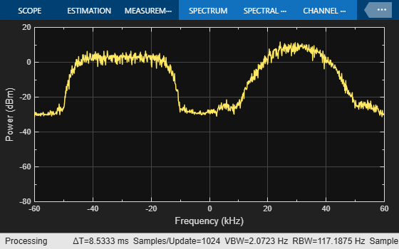
Intra-band contiguous aggregation results in a signal that has two original signals, each 60 kHz wide, occupying two contiguous bands of 60 kHz each. In intra-band non-contiguous aggregation, the two signals occupy non-contiguous bands as shown by the gap between the signal spectra in the Intra-Band Non-Contiguous Spectrum Analyzer. Inter-band non-contiguous aggregation can be similarly achieved by appropriate frequency shifts of the signals.
Summary and Further Exploration
This example illustrates a technique to model the carrier aggregation that is used by most modern wireless communications standards to increase data rates. A System object is used to encapsulate the necessary processing of interpolation, frequency shift and signal combining. You can explore further in various ways:
Use baseband signals with different bandwidths. As
MultibandCombinerSystem object requires all input signals to have the same sample rate, resample one or more signals to bring all baseband signals to the same rate before usingMultibandCombinerSystem object.Aggregate more than two baseband signals.
Use different aggregation bands and carriers to model inter-band non-contiguous aggregation.
Also, explore the MultibandCombiner System object to study and possibly alter the processing necessary for carrier aggregation. Besides configuring the object to automatically compute the output sample rate by setting the OutputSampleRateSource to "Auto", you can also interpolate the baseband input signals to the rate you desire before using the MultibandCombiner object, then set the OutputSampleRateSource to "Property" and set the "OutputSampleRate" equal to "InputSampleRate" which configures the System object to not perform any interpolation.