Generate Digital Data Using a Shared Clock
R2026bThis example shows how to generate clocked digital data by sharing the clock from the analog output subsystem with the digital subsystem on an NI™ device. The device synchronizes the digital output with the analog subsystem automatically, and you do not need any physical wiring to share the clock. For more information, see Automatic Synchronization.
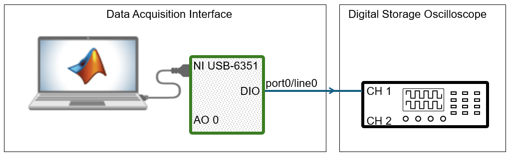
Create DataAcquisition Object and Add Digital Output
Channel
Create a DataAcquisition object and add a digital output line from port
0 line 0 on Dev1. This
example uses a NI USB-6351 with device ID Dev1.
d = daq("ni");
addoutput(d,"Dev1","Port0/Line0","Digital")
Note
Not all devices support clocked digital I/O operations with hardware timing. For these
devices you can use software timed operations with single scan calls to read and
write.
Devices that support clocked digital I/O operations might not support them on all ports. Check your device specifications.
Add Analog Output Channel to Supply Shared Clock
Add an analog output channel to your DataAcquisition object using
the addoutput
function.
addoutput(d,"Dev1",0,"Voltage");
d.Channels
ans =

    Index    Type     Device       Channel       Measurement Type          Range                  Name
    _____    _____    ______    _____________    ________________    __________________    __________________

      1      "dio"    "Dev1"    "port0/line0"    "OutputOnly"         "n/a"                 "Dev1_port0/line0"
      2      "ai"     "Dev1"    "ai0"            "Voltage (Diff)"    "-10 to +10 Volts"    "Dev1_ai0"
Configure Scan Rate and Generate Output Data
The device generates digital data at the scan rate determined by its analog subsystem. Configure the scan rate and specify the data to output. In this example, 200 samples of digital data is generated in 2 seconds.
d.Rate = 100;
Tsec = 2;
dataAO = zeros(Tsec*d.Rate,1);
dataDO = randi([0 1],Tsec*d.Rate,1);
Output the generated digital data to the hardware channel using the write
function.
write(d, [dataDO dataAO]);
Verify Generated Output
You can check the NumscansOutputByHardware property to verify
that the device has generated the specified data. You can also connect the digital
output channel to an oscilloscope to view the generated output.
d
d =

DataAcquisition using National Instruments(TM) hardware:

                     Running: 0
                        Rate: 100
           NumScansAvailable: 0
            NumScansAcquired: 0
              NumScansQueued: 0
    NumScansOutputByHardware: 200
                   RateLimit: [0.1000 2.8571e+06]

Show channels
Show properties and methods
