Board-Specific Setup Information
Note
For setting up the boards, you do not need an Ethernet cable or an SD card.
Xilinx Zynq UltraScale++ MPSoC ZCU102 FPGA Development Board
Set up the Xilinx Zynq UltraScale+ MPSoC ZCU102 evaluation kit as shown in the figure below:

To setup the board:
Plug in the power cord. If using JTAG connect the FPGA board to the host computer using a JTAG cable. If using Ethernet connect the FPGA board to the host computer using an Ethernet cable.
Configure
SW6switch which is shown in the image below:
Use the configuration table below to configure the switch settings:
Boot Mode Mode Pins [3:0] SW6Switch Position [3:0]JTAG0, 0, 0, 0 on, on, on, on QSPI320, 0, 1, 0 on, on, off, on SD1, 1, 1, 0 off, off, off, on Ethernet1, 1, 1, 0 off, off, off, on The
SW6default position isQSPI32. For theSW6DIP switch moving the switch towards theONlabel is a 0.To learn more about the ZCU102 hardware setup, please refer to Xilinx documentation
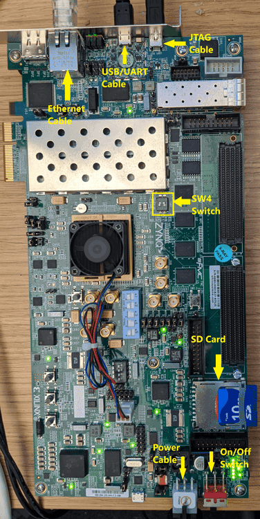
Xilinx Zynq -7000 ZC706 Evaluation Board
To set up the Xilinx® Zynq® -7000 ZC706 board:
Configure
SW4shown in the image below, and to use Digilent USB-TO-JTAG interface using the following configuration table:Configuration Source SW4switch 1SW4switch 2None 0 0 Cable Connector J3 1 0 Digilent USB-TO-JTAG Interface 0 1 JTAG (flying lead)Header J62 1 1 Plug in the power cord and then connect the host computer to the FPGA board by using a JTAG cable as shown in the image below:
To learn more about the board configuration, see Xilinx ZC706 Evaluation Board User Guide.