fdesign.ciccomp
CIC compensator filter specification object
Syntax
d= fdesign.ciccomp

d= fdesign.ciccomp(d,nsections,rcic)

d= fdesign.ciccomp(...,spec)

h = fdesign.ciccomp(...,spec,specvalue1,specvalue2,...)
Description
d= fdesign.ciccomp constructs
a CIC compensator specifications object d, applying
default values for the properties Fpass, Fstop, Apass, and Astop.
In this syntax, the filter has two sections and the differential delay
is 1.
Using fdesign.ciccomp with design method
creates a System object™, if the 'SystemObject' flag
is set to true.
d= fdesign.ciccomp(d,nsections,rcic) constructs
a CIC compensator specifications object with the filter differential
delay set to d, the number of sections in the filter
set to nsections, and the CIC rate change factor
set to rcic. The default values of these parameters
are: the differential delay equal to 1, the number of sections equal
to 2, and the CIC rate change factor equal to 1.
If the CIC rate change factor is equal to 1, the filter passband response is an inverse sinc that is an approximation to the true inverse passband response of the CIC filter.
If you specify a CIC rate change factor not equal to 1, the filter passband response is an inverse Dirichlet sinc that matches exactly the true inverse passband response of the CIC filter.
d= fdesign.ciccomp(..., constructs
a CIC Compensator specifications object and sets its spec)Specification property
to spec. Entries in the spec represent
various filter response features, such as the filter order, that govern
the filter design. Valid entries for spec are
shown in the list below. The entries are not case sensitive.
'fp,fst,ap,ast'(defaultspec)'n,fc,ap,ast''n,fp,ap,ast''n,fp,fst''n,fst,ap,ast'
The filter specifications are defined as follows:
ap— amount of ripple allowed in the pass band in decibels (the default units). Also called Apass.ast— attenuation in the stop band in decibels (the default units). Also called Astop.fc— cutoff frequency for the point 6 dB point below the passband value. Specified in normalized frequency units.fp— frequency at the end of the pass band. Specified in normalized frequency units. Also called Fpass.fst— frequency at the start of the stop band. Specified in normalized frequency units. Also called Fstop.n— filter order.
In graphic form, the filter specifications look like this:

Regions between specification values like fp and fst are
transition regions where the filter response is not explicitly defined.
The filter design methods that apply to a CIC compensator specifications
object change depending on the Specification. Use designmethods to determine which design
method applies to an object and its specification.
h = fdesign.ciccomp(...,spec,specvalue1,specvalue2,...) constructs
an object and sets the specifications in the order they are specified
in the spec input when you construct the object.
Designing CIC Compensators
Typically, when they develop filters, designers want flat passbands and transition regions that are as narrow as possible. CIC filters present a (sinx/x) profile in the passband and relatively wide transitions.
To compensate for this fall off in the passband, and to try to reduce the width of the transition region, you can use a CIC compensator filter that demonstrates an (x/sinx) profile in the passband. fdesign.ciccomp is specifically tailored to designing CIC compensators.
You can design a compensator for CIC filter using differential delay, d, number of sections, numberofsections, and the usable passband frequency, Fpass.
By taking the number of sections, passband, and differential delay from your CIC filter and using them in the definition of the CIC compensator, the resulting compensator filter effectively corrects for the passband droop of the CIC filter, and narrows the transition region.
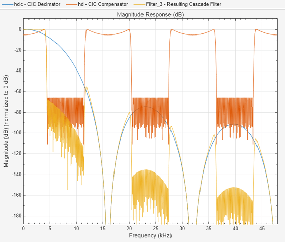
As a demonstration of this concept, this example creates a CIC decimator and its compensator. Visualize the magnitude response of the CIC filter and a compensator for that filter.
fs = 96e3;   % Input sampling frequency.
fpass = 4e3; % Frequency band of interest.
m = 6;  % Decimation factor.
hcic = design(fdesign.decimator(m,'cic',1,fpass,60,fs),'SystemObject',true);
hd = design(fdesign.ciccomp(hcic.DifferentialDelay, ...
            hcic.NumSections,fpass,4.5e3,.1,60,fs/m),'SystemObject',true);
hvft = filterAnalyzer(hcic,hd,...
cascade(hcic,hd),ReferenceFilter=false,SampleRates=[96e3 96e3/m 96e3],NormalizeMagnitude=true);
setLegendStrings(hvft,["CIC Decimator","CIC Compensator","Resulting Cascade Filter"]);
Examples
Designed to compensate for the rolloff inherent in CIC filters, CIC compensators can improve the performance of your CIC design. This example designs a compensator d with five sections and a differential delay equal to one. The plot displayed after the code shows the increasing gain in the passband that is characteristic of CIC compensators, to overcome the droop in the CIC filter passband. Ideally, cascading the CIC compensator with the CIC filter results in a lowpass filter with flat passband response and narrow transition region.
h = fdesign.ciccomp;
set(h,NumberOfSections=5,DifferentialDelay=1);
cicComp = design(h,'equiripple',SystemObject=true);
filterAnalyzer(cicComp)
This compensator would work for a decimator or interpolator that had differential delay of 1 and 5 sections.
Version History
Introduced in R2011a