Lowpass IIR Filter Design in Simulink
This example shows how to design classic lowpass IIR filters in Simulink®.
The example first presents filter design using filterBuilder. The
critical parameter in this design is the cutoff frequency, the frequency at which filter
power decays to half (-3 dB) the nominal passband value. The example
shows how to replace a Butterworth design with either a Chebyshev or elliptic filter of
the same order and obtain a steeper roll-off at the expense of some ripple in the
passband and/or stopband of the filter. The example also explores minimum-order
designs.
The example then shows how to design and use lowpass filters in Simulink using the interface available from the Lowpass Filter block.
Finally, the example showcases the Variable Bandwidth IIR Filter, which enables you to change the filter cutoff frequency at run time.
filterBuilder
filterBuilder starts user
interface for building filters. filterBuilder uses a
specification-centered approach to find the best algorithm for the desired response.
It also enables you to create a Simulink block from the specified design.
To start designing IIR lowpass filter blocks using
filterBuilder, execute the command
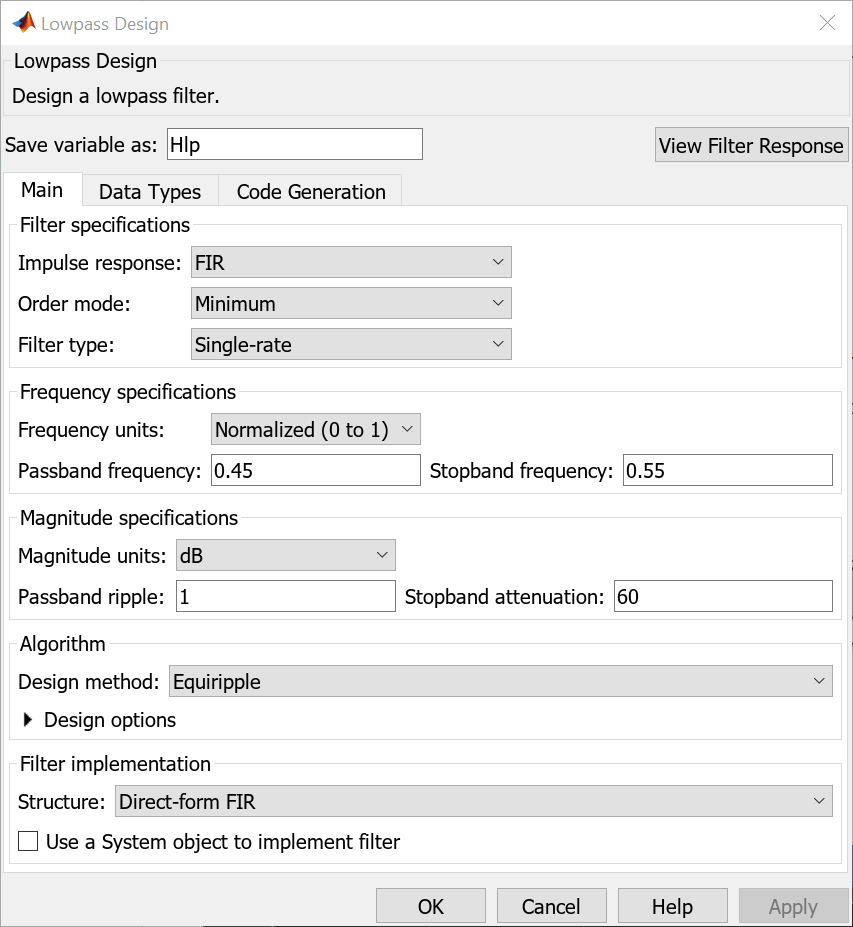
filterBuilder('lp'). A Lowpass Design dialog box
opens.
Butterworth Filter
Design an eighth order Butterworth lowpass filter with a cutoff frequency of 5 kHz, assuming a sample rate of 44.1 KHz.
Set the Impulse response to IIR, the Order mode to Specify, and the Order to 8. To specify the cutoff frequency, set Frequency constraints to Half power (3 dB) frequency. To specify the frequencies in Hz, set Frequency units to Hz, Input sample rate to 44100, and Half power (3 dB) frequency to 5000. Set the Design method to Butterworth.

Click Apply. To visualize the filter's frequency response, click View Filter Response. The filter is maximally flat. There is no ripple in the passband or in the stopband. The filter response is within the specification mask (the red dotted line).

Generate a block from this design and use it in a model.
Open the ex_iir_design model. In Filter Builder, on the Code Generation tab, click Generate Model. In the Export to Simulink window, specify the Block name as Butter and Destination as Current. You can also choose to build the block using basic elements such as delays and gains, or use one of the DSP System Toolbox filter blocks. This example uses the filter block.

Click Realize model to generate the Simulink block. You can now connect the block input and output ports to the source and sink blocks in the ex_iir_design model.

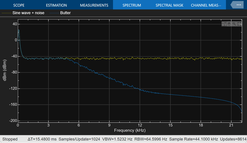
In the model, a noisy sine wave sampled at 44.1 kHz passes through the filter. The sine wave is corrupted by Gaussian noise with zero mean and a variance of 10e-5. Run the model. The view in the Spectrum Analyzer shows the original and filtered signals.
Chebyshev Type I Filter
Now design a Chebyshev Type I filter. A Chebyshev type I design allows you to control the passband. There are still no ripples in the stopband. Larger ripples enable a steeper roll-off. In this model, the peak-to-peak ripple is specified as 0.5 dB.
In the Main tab of Filter Builder, set the
Magnitude Constraints to
Passband ripple.Passband ripple to
0.5.Design method to
Chebyshev type
                                I
.
Click Apply and then click View Filter Response.
Zooming in on the passband, you can see that the ripples are contained in the range [-0.5, 0] dB.

Similar to the Butterworth filter, you can generate a block from this design by clicking Generate Model on the Code Generation tab, and then clicking Realize model.
Chebyshev Type II Filter
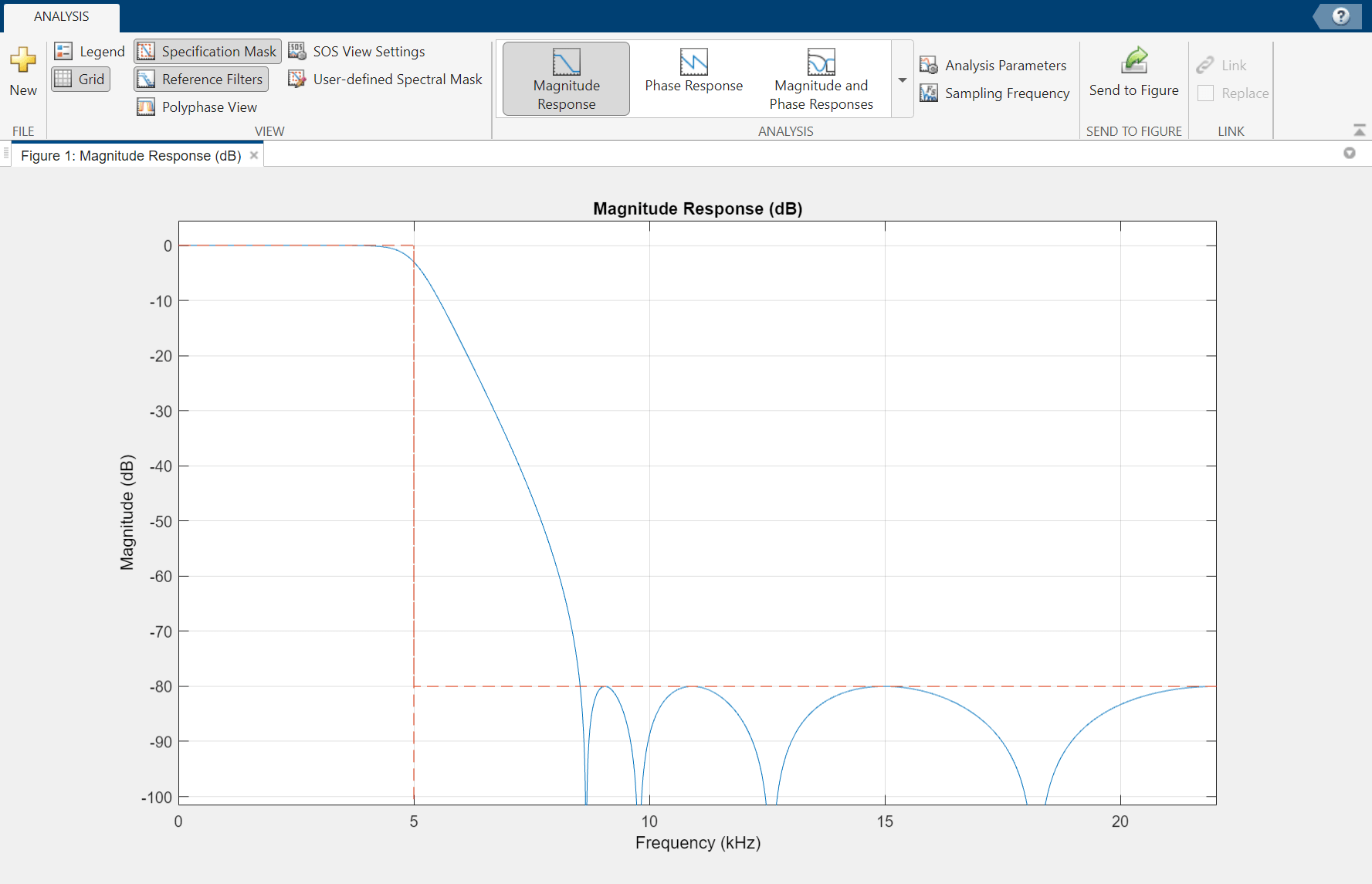
A Chebyshev type II design allows you to control the stopband attenuation. There
are no ripples in the passband. A smaller stopband attenuation enables a steeper
roll-off. In this example, the stopband attenuation is 80 dB. Set
the Filter Builder
Main tab as shown, and click
Apply.

Click View Filter Response.
To generate a block from this design, on the Code Generation tab, click Generate Model, and then click Realize model.
Elliptic Filter
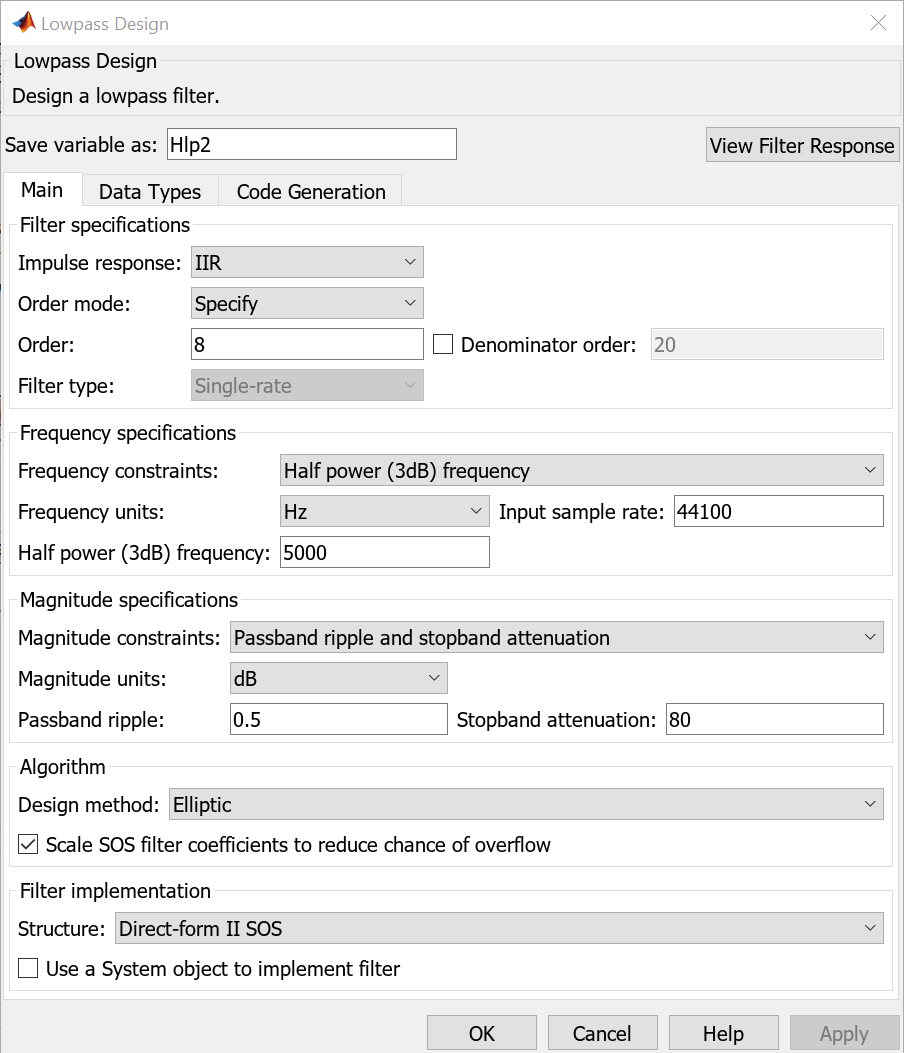
An elliptic filter can provide steeper roll-off compared to previous designs by allowing ripples in both the stopband and passband. To illustrate this behavior, use the same passband and stopband characteristics specified in the Chebyshev designs. Set the Filter Builder Main tab as shown, and click Apply.

To generate a block from this design, on the Code Generation tab, click Generate Model, and then click Realize model.
Minimum-Order Designs
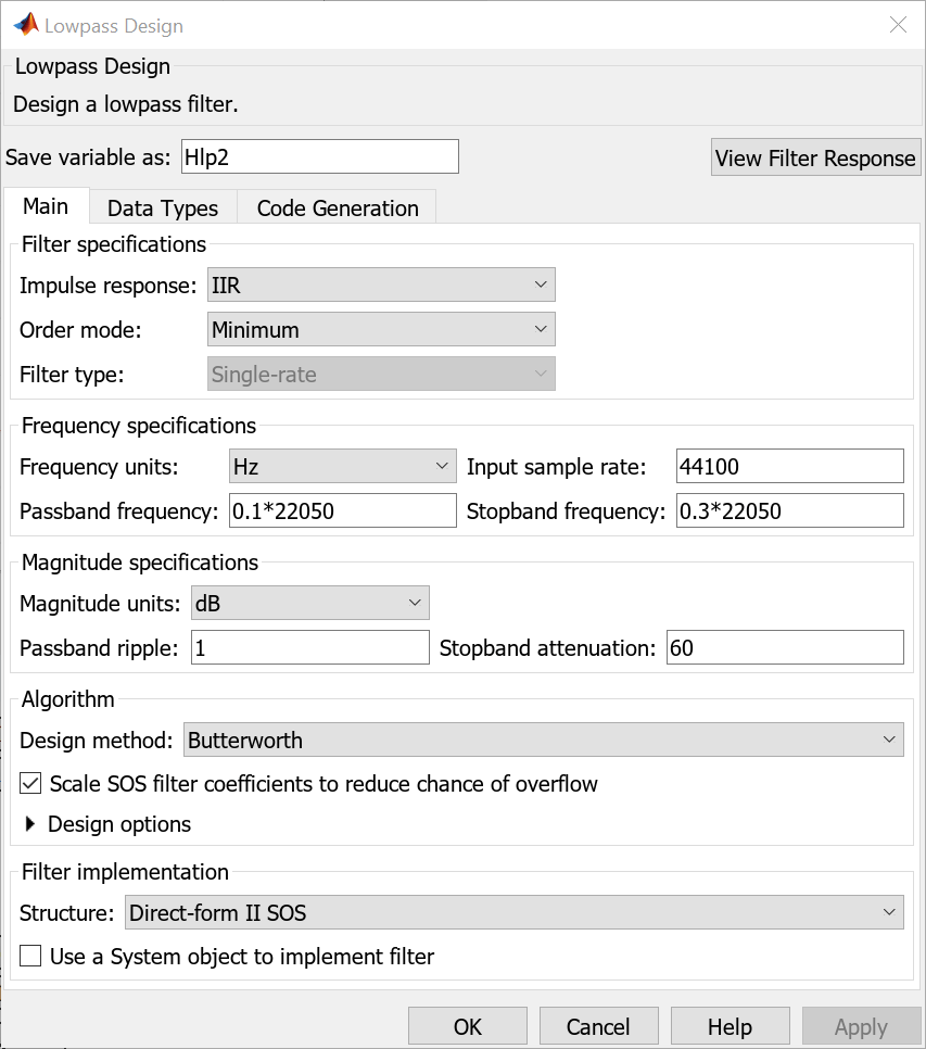
To specify the passband and stopband in terms of frequencies and the amount of
tolerable ripple, use a minimum-order design. As an example, verify that the
Order mode of the Butterworth filter is set to
Minimum, and set Design method
to Butterworth. Set the passband and stopband frequencies
to 0.1*22050 Hz and 0.3*22050 Hz, and the
passband ripple and the stopband attenuation to 1 dB and
60 dB, respectively. A seventh-order filter is necessary to
meet the specifications with a Butterworth design. By following the same approach
for other design methods, you can verify that a fifth-order filter is required for
Chebyshev type I and type II designs. A fourth-order filter is sufficient for the
elliptic design.
This figure shows the magnitude response for the seventh-order Butterworth design.

The pole-zero plot for the seventh-order Butterworth design shows the expected clustering of 7 poles around an angle of zero radians on the unit circle and the corresponding 7 zeros at an angle of π radians.

Lowpass Filter Block
As an alternative to Filter Builder, you can use the Lowpass Filter block in your Simulink model. The Lowpass Filter block combines the design and implementation stages into one step. The filter designs its coefficients using the elliptical method, and allows minimum order and custom order designs.
Open the ex_lowpass model. The Lowpass Filter block filters a noisy sine wave signal sampled at 44.1 kHz. The original and filtered signals are displayed in a spectrum analyzer.


The Lowpass Filter block allows you to design filters that approximate arbitrarily close to Butterworth and Chebyshev filters. To approximate a Chebyshev Type I filter, make the stopband attenuation arbitrarily large, for example, 180 dB. To approximate a Chebyshev Type II filter, make the passband ripple arbitrarily small, for example, 1e-4. To approximate a Butterworth filter, make the stopband attenuation arbitrarily large and the passband ripple arbitrarily small.
You can specify the sample rate in normalized frequency units (ranging from 0 to 1) by setting the Sample rate mode parameter to Use normalized frequency (0 to 1).
Variable Bandwidth IIR Filter Block
You can also design filters that allow you to change the cutoff frequency at run time. The Variable Bandwidth IIR Filter block can be used for such cases. Refer to the Tunable Lowpass Filtering of Noisy Input in Simulink example for a model that uses this block.