FCC Peripheral Configuration
Description
Add-On Required: This feature requires the Embedded Coder Support Package for Infineon AURIX TC4x Microcontrollers add-on.
View and edit the map of peripherals in the Infineon® AURIX™ model to the hardware peripherals.
Using the Hardware Mapping tool, you can:
View and edit the configuration parameters for FCC block.
Check for any conflicts between the peripherals.
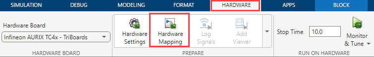
Open the FCC Peripheral Configuration
In the Hardware tab of the simulink model, click Hardware Mapping.
Parameters
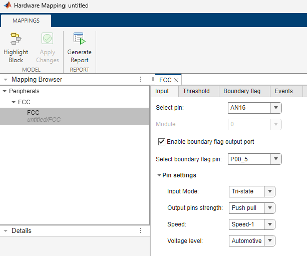
Input
Select the input pin number.
Select this option to enable connection to the digital port to output the status of the boundary flag.
Select pin number for the digital port that outputs the boundary flag status.
Dependencies
To enable this parameter, select the Enable boundary flag output port parameter.
Input > Pin settings
Select the input mode for the FCC pin.
Select the strength of output pins.
Dependencies
To enable this parameter, select the Enable boundary flag output port parameter.
Select the speed of FCC pin.
Select the voltage level of the FCC pin.
Threshold > Threshold trigger
Specify the initial value for the threshold update.
Dependencies
To enable this parameter, set the Mode parameter to
Normal or Hysteresis
in the FCC block in the Simulink® model.
Set the type of trigger to Software trigger - Sample Time or Hardware trigger to update the threshold value during run time.
Dependencies
To enable this parameter, set the Mode parameter to
Normal or Hysteresis
in the FCC block in the Simulink model.
Select the source of the hardware trigger to update the threshold value during run time.
Dependencies
To enable this parameter, set the Threshold update on
parameter to Hardware trigger.
Select hardware trigger to update the threshold value during run time.
Dependencies
This parameter appears only if you select the Threshold update
on parameter as Hardware
trigger.
Select the type of hardware trigger edge to update the threshold value during run time.
Dependencies
To enable this parameter, set the Threshold update on
parameter to Hardware trigger.
Specify the trigger delay to update the threshold value during run time.
Dependencies
To enable this parameter, set the Threshold update on
parameter to Hardware trigger.
Threshold > Hysteresis
Specify the upper delta limit for the threshold value in the hysteresis mode of operation.
Dependencies
To enable this parameter, set the Mode parameter to
Hysteresis in the FCC block in the Simulink model.
Specify the lower delta limit for the threshold value in the hysteresis mode of operation.
Dependencies
To enable this parameter, set the Mode parameter to
Hysteresis in the FCC block in the Simulink model.
Threshold > Ramp
Specify the initial threshold value at the start of the ramp mode of operation.
Dependencies
To enable this parameter, set the Mode parameter to
Ramp in the FCC block in the Simulink model.
Specify the initial threshold value at the end of the ramp mode of operation.
Dependencies
To enable this parameter, set the Mode parameter to
Ramp in the FCC block in the Simulink model.
Specify the initial step width of the ramp.
Dependencies
To enable this parameter, set the Mode parameter to
Ramp in the FCC block in the Simulink model.
Specify the initial step size of the ramp.
Dependencies
To enable this parameter, set the Mode parameter to
Ramp in the FCC block in the Simulink model.
Select the trigger source to start the ramp.
Dependencies
To enable this parameter, set the Mode parameter to
Ramp in the FCC block in the Simulink model.
Specify the trigger or source to end of the ramp. You can select the
Boundary flag transition or End of threshold value option if
you set the Ramp start on parameter to Software
trigger - Sample time.
Dependencies
To enable this parameter, set the Mode parameter to
Ramp in the FCC block in the Simulink model.
Threshold > Trigger
Select the source of the hardware trigger.
Dependencies
To enable this parameter, set the Ramp start on
parameter to Hardware trigger.
Select the hardware trigger for the threshold update in the ramp mode.
Dependencies
To enable this parameter, set the Ramp start on
parameter to Hardware trigger or Ramp end
on parameter as Hardware trigger or End of threshold
value.
Select the type of the hardware trigger edge for the threshold update in the ramp mode.
Dependencies
To enable this parameter, set the Ramp start on
parameter to Hardware trigger or the Ramp
end on parameter to Hardware trigger or End of
threshold value.
Specify the trigger delay for threshold update in ramp mode.
Dependencies
To enable this parameter, set the Ramp start on
parameter to Hardware trigger or the Ramp
end on parameter to Hardware trigger or End of
threshold value.
Boundary flag
Specify the number of glitches to filter out in the input signal.
Activate boundary flag based on threshold value.
Boundary flag > Gate
Specify when to enable the boundary flag.
Specify the source of gate signal to enable the boundary flag.
Note
Ensure that you have configured the appropriate trigger from the PWM block.
Dependencies
To enable this parameter, set the Flag enable on
parameter to Gate High or Gate
Low.
Select hardware trigger to enable the boundary flag.
Dependencies
To enable this parameter, set the Flag enable on
parameter to Gate High or Gate
Low.
Select the type of hardware trigger edge to enable the boundary flag
Dependencies
To enable this parameter, set the Flag enable on
parameter to Gate High or Gate
Low.
Specify the gate trigger delay to enable the boundary flag.
Dependencies
To enable this parameter, set the Flag enable on
parameter to Gate High or Gate
Low.
Boundary flag > Boundary flag connection
Specify the number of boundary flag connections.
Boundary flag > Connection #
Specify the module for boundary flag connections.
Dependencies
To enable this parameter, set the Number of connections parameter to a value greater than 0.
Specify the channels for the PWM module selected.
Dependencies
To enable this parameter, set the Number of connections parameter to a value greater than 0.
Events > Service request - 0
Service request based on boundary flag edges.
Events > Service request - 1
Service request based on the mode of the threshold update. You can select the
option End of ramp in Ramp mode and
New threshold update in Normalor
Hysteresis mode of operation.
Version History
Introduced in R2024a
See Also
MATLAB Command
You clicked a link that corresponds to this MATLAB command:
Run the command by entering it in the MATLAB Command Window. Web browsers do not support MATLAB commands.
Seleccione un país/idioma
Seleccione un país/idioma para obtener contenido traducido, si está disponible, y ver eventos y ofertas de productos y servicios locales. Según su ubicación geográfica, recomendamos que seleccione: .
También puede seleccionar uno de estos países/idiomas:
Cómo obtener el mejor rendimiento
Seleccione China (en idioma chino o inglés) para obtener el mejor rendimiento. Los sitios web de otros países no están optimizados para ser accedidos desde su ubicación geográfica.
América
- América Latina (Español)
- Canada (English)
- United States (English)
Europa
- Belgium (English)
- Denmark (English)
- Deutschland (Deutsch)
- España (Español)
- Finland (English)
- France (Français)
- Ireland (English)
- Italia (Italiano)
- Luxembourg (English)
- Netherlands (English)
- Norway (English)
- Österreich (Deutsch)
- Portugal (English)
- Sweden (English)
- Switzerland
- United Kingdom (English)