TMADC
Libraries:
Embedded Coder Support Package for Infineon AURIX TC4x
Microcontrollers /
AURIX TC4x
Description
Measure the voltage of an analog input pin.
The Time Multiplexed Analog to Digital Converter (TMADC) block outputs the voltage as
a 12-bit value and the output port is an array N x 1 where
N is defined based on the number of channels selected.
Examples
Field-Oriented Control of BLDC with Encoder Using Infineon AURIX Microcontrollers
Implement the field-oriented control (FOC) technique to control the speed of a three-phase brushless DC (BLDC) motor. The FOC algorithm requires rotor position feedback, which is obtained by using an encoder sensor. For more details about FOC, see Field-Oriented Control (FOC) (Motor Control Blockset).
Analyze Sensorless Observers for Field-Oriented Control Using Multiple Cores of Infineon AURIX
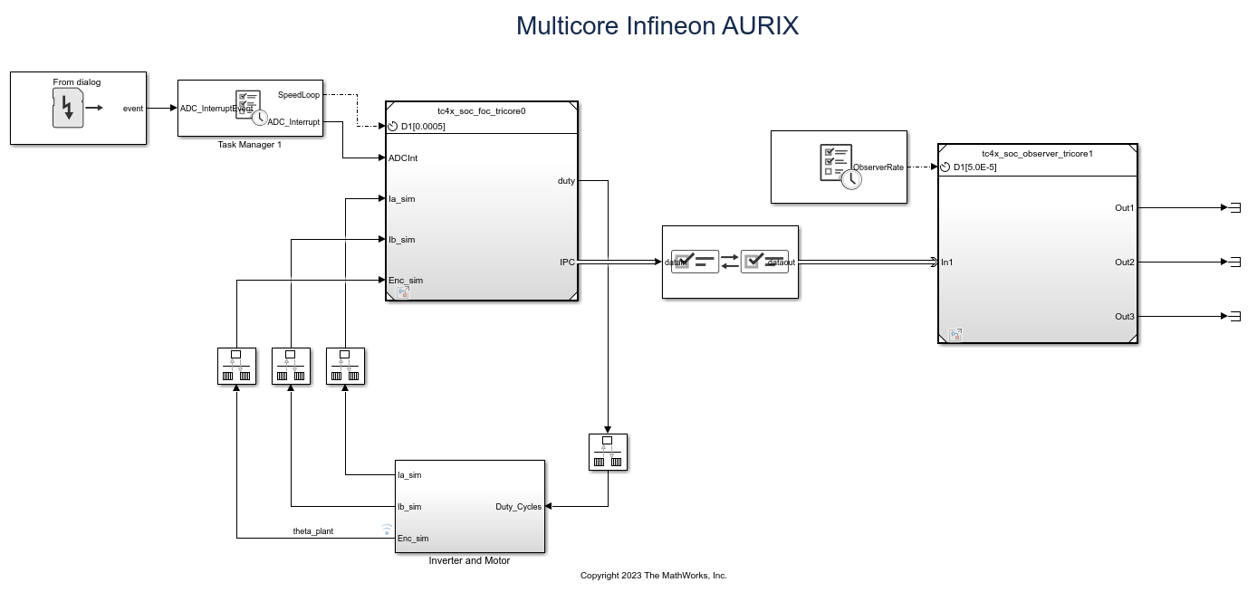
Use Embedded Coder® Support Package for Infineon® AURIX™ Microcontrollers for sensorless field-oriented control using multiple cores of an Infineon AURIX microcontroller board. This example uses a top-level model and two referenced models. You use the TriCore0 referenced model to implement a sensor-based field-oriented control (FOC) technique to control the speed of a three-phase brushless DC (BLDC) motor. You use the TriCore1 referenced model to implement and analyze different sensorless algorithms, such as the algorithms implemented in the Flux Observer (Motor Control Blockset), Sliding Mode Observer (Motor Control Blockset), and Extended EMF Observer (Motor Control Blockset) blocks.
Accelerate AI Based Software Development on Infineon AURIX TC4x Microcontroller
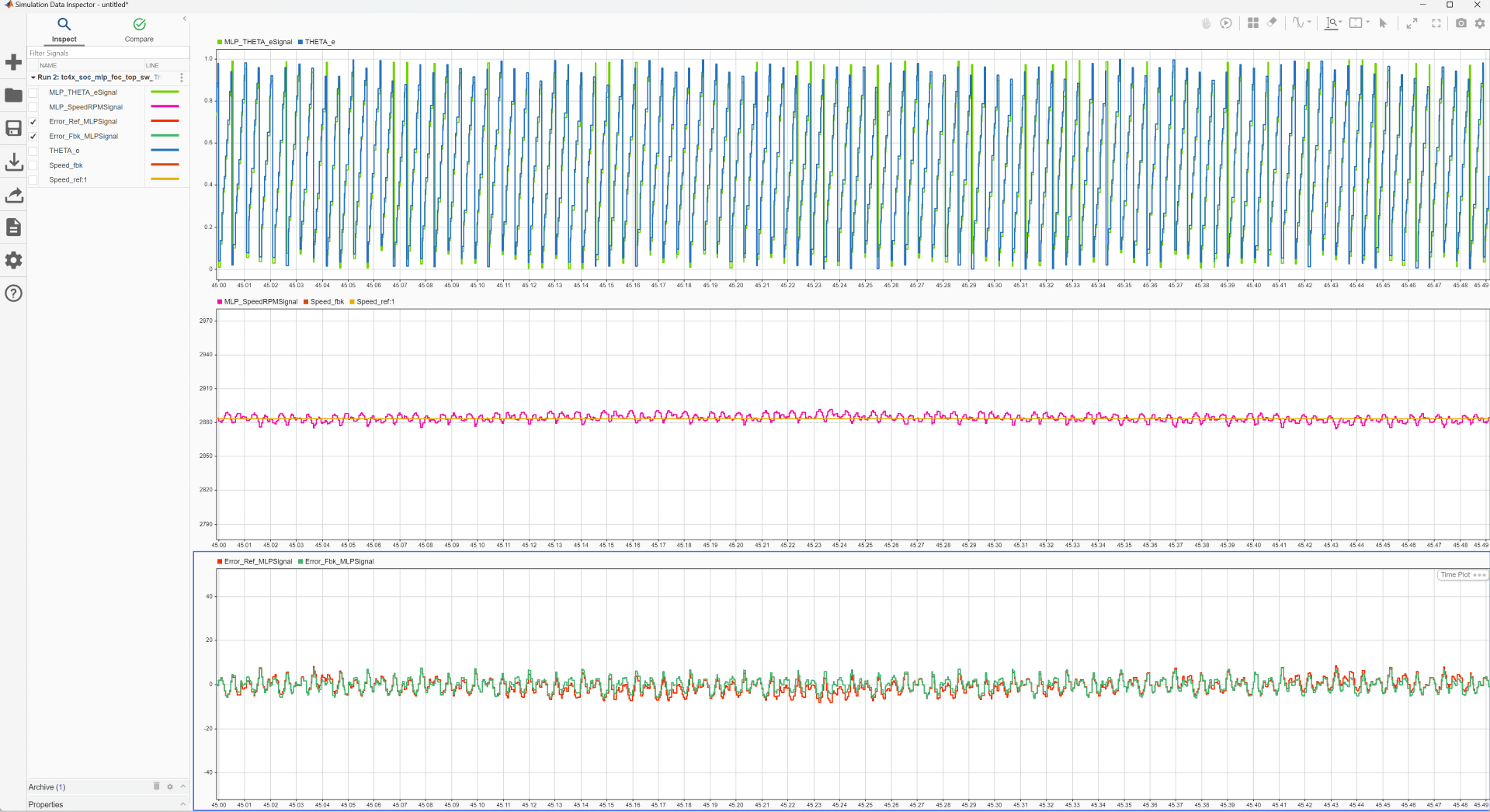
Implement AI based motor control functions using the Model-Based Design approach by deploying a multi-layer perceptron (MLP) neural network on the Infineon® AURIX™ TC4x microcontroller.
Ports
Input
Triggers the TMADC input pin for conversion via software trigger.
From trigger port when mode is set trigger only enables you to provide the sample time.
1—TMADC start of conversion is triggered0—TMADC start of conversion is not triggered
Dependencies
To view this port, set the Mode parameter to
Trigger only.
Data Types: single | double | int8 | int16 | int32 | uint8 | uint16 | uint32 | Boolean
This port receives SoC Blockset™ message from the interface blocks and the TMADC block converts this message and outputs it at the result port during simulation.
Dependencies
To view this input port, set the Mode to
Trigger and read or Read
results only and select the Enable
simulation port parameter and set the port type as
SoC Data (Message based).
The simulation-only Simulink® signal input port acts as a pass-through for the output of the TMADC block during simulation.
Dependencies
To view this port, set Mode to
Trigger and read or Read
results only and select the Enable
simulation port parameter and set the port type to
Signal.
Output
The block outputs the voltage as a 12-bit value and the output port is
an array N x 1 where N is
defined based on the number of channels selected.
Dependencies
To enable this port, set the Mode parameter
to Trigger and read or Read
results only.
Data Types: uint16
The block outputs the status of read operation at this port as one of these values:
0—No error in reading the result after successful trigger for the corresponding channel1—Error in reading the result after successful trigger for the corresponding channel
Dependencies
To enable this port, set the Mode to
Read
                                    results only
and select the
Enable status port parameter.
Data Types: double
The port outputs the status of the 16-bit counter value of timestamp counter.
Dependencies
To enable this port, select the Enable timestamp parameter.
Data Types: Boolean
This port outputs an event message at each trigger to start the conversion during simulation.
Dependencies
To view this port, set the Mode to
Trigger only and select the
Enable simulation port parameter, and set
the port type to SoC Data (Message
based).
This port outputs the data received at trigger input port as a signal during simulation.
Dependencies
To view this port, set the Mode to
Trigger only and select the
Enable simulation port parameter, and set
the port type to Signal.
Parameters
Select one of these operation modes:
Trigger and read—Select this option to trigger conversion at every sample time. The block waits until the conversion is complete and outputs the results. This option enables the output port result.Trigger only—Select this option to trigger the selected channel via a software trigger. This option enables the input port trigger. As the block does not show the conversion results in this mode, you have to use another TMADC block with the Mode parameter set toRead results onlyto display the conversion results.Read results only—Select this option for the block to read the result at the selected channel. The block outputs0at the status port if it is able to read the result and1otherwise. This option enables the output port result.
If you set the Mode to Trigger and
read, then select the required number of channels ranging
between 1 through 16. The number of
channels are limited to 1 if you set the Mode to
Trigger only or Read results
only.
Select to enable the timestamp.
When you select the Enable timestamp parameter, the
block configures an additional output port, timestamp similar to result port
to read the timestamp.
Note
TMADC module has 16-bit timestamp counter which resets after every counter overflow.
Enable timestamp parameter is not available when mode is set to
Trigger only.
When you select this parameter, the block configures the status output port. The status port outputs the status of the conversion result.
Dependencies
To enable this port, set the Mode parameter to
Read results only.
Specify in seconds how often the block should read the analog pin(s).
When you specify this parameter as -1, Simulink determines the best sample time for the block based on the
block context within the model.
Dependencies
To enable the Sample time parameter, set the
Mode parameter to either Trigger
and read or Read results
only.
Select this parameter to enable peripheral simulation capability.
Select this parameter to configure either the compatible or the Simulink signal based simulation ports to enable peripheral simulation capability.
Dependencies
To view this parameter, select the Enable simulation port parameter.
Version History
Introduced in R2022b
See Also
MATLAB Command
You clicked a link that corresponds to this MATLAB command:
Run the command by entering it in the MATLAB Command Window. Web browsers do not support MATLAB commands.
Seleccione un país/idioma
Seleccione un país/idioma para obtener contenido traducido, si está disponible, y ver eventos y ofertas de productos y servicios locales. Según su ubicación geográfica, recomendamos que seleccione: .
También puede seleccionar uno de estos países/idiomas:
Cómo obtener el mejor rendimiento
Seleccione China (en idioma chino o inglés) para obtener el mejor rendimiento. Los sitios web de otros países no están optimizados para ser accedidos desde su ubicación geográfica.
América
- América Latina (Español)
- Canada (English)
- United States (English)
Europa
- Belgium (English)
- Denmark (English)
- Deutschland (Deutsch)
- España (Español)
- Finland (English)
- France (Français)
- Ireland (English)
- Italia (Italiano)
- Luxembourg (English)
- Netherlands (English)
- Norway (English)
- Österreich (Deutsch)
- Portugal (English)
- Sweden (English)
- Switzerland
- United Kingdom (English)


