Code Verification and Validation with PIL Using PPU
This example shows you how to use Embedded Coder® Support Package for Infineon® AURIX™ TC4x Microcontrollers for code verification and validation using processor-in-the-loop (PIL), for top model.
In this example you will learn how to configure a Simulink® model to run PIL. In a PIL simulation, the generated code runs on the TC4x TriBoards. The results of the PIL simulation are transferred to Simulink to verify the numerical equivalence of the simulation and the code generation results. The PIL verification process is a crucial part of the development cycle to ensure that the behavior of the deployment code matches the design.
This example introduces the Simulink code generation and verification workflow by showing you how to configure a Simulink model to run PIL simulations on the Infineon AURIX TC4x TriBoards.
Prerequisites
Complete the Getting Started with Embedded Coder Support Package for Infineon AURIX TC4x Microcontrollers example
Required Hardware
Infineon AURIX TC4x - TriBoards
Micro-USB cable
Configure Model
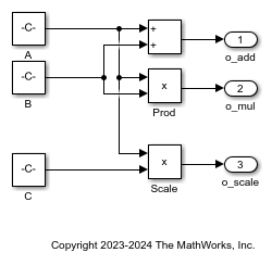
1. Open the soc_tc4x_ppu_pil.slx model. The model is pre-configured for Infineon AURIX TC4x hardware board.
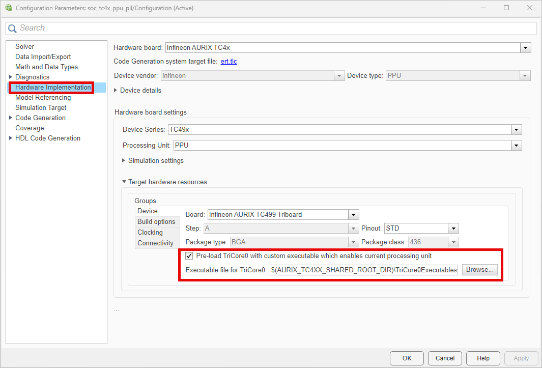
2. To run the model on other Infineon AURIX processors, press Ctrl+E to open the Configuration Parameters dialog box and select the required hardware board by navigating to Hardware Implementation > Hardware board. Under Hardware board settings, expand Target hardware resources and set the Series and Package class parameters to match your hardware board.
3. Navigate to Hardware Implementation > Hardware board settings > Target hardware resources > Device and enable Pre-load TriCore0 with custom executable which enables current processing unit parameter. The TriCore0 is the principal processing unit that handles system initialization, boot processes, and critical control tasks in the Infineon AURIX microcontrollers. Application models using processing units other than TriCore 0 must enable Pre-load TriCore0 with custom executable which enables current processing unit parameter to initialize these processing units.
Choosing a Communication Interface for PIL Simulation
Choose a communication interface by following the steps below:
Navigate to Hardware Implementation > Target Hardware Resources > Connectivity > Serial port in MATLAB preferences and select the COM port of host computer for PIL simulations.

To find the COM port number of the USB Serial Port showing in your host computer, browse to Device Manager > Ports (COM & LPT) to find the COM port.

Verifying Top Model Code Using PIL
This example shows how to verify the generated code for a model by running a PIL simulation. With this approach:
You can verify code generated for a top model
You must configure the model to load test vectors or stimulus inputs from the MATLAB® workspace
You can easily switch the entire model between normal and PIL simulation mode
1. Open the soc_tc4x_ppu_pil.slx model.
2. Choose the COM port.
3. Run the top model PIL simulation.
a. Open the Apps tab and select SIL/PIL Manager.
b. On the SIL/PIL tab, set Mode to Automated Verification, SIL/PIL Mode to Processor-in-the-loop(PIL), and click Run Verification.

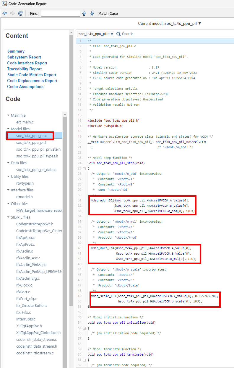
4. Simulink generates code generation report after the completion of PIL simulation. Analyze the replacements and misses in the code replacement viewer.

5. You can view the CRL entries in the code replacement viewer.

6. Analyze the generated code to understand the code replacements used for the model.
Note
You can ignore the termination error message, which might occur during the PIL simulation.
