Using the Analog to Digital Converter Block to Support STMicroelectronics STM32 Processor Based Boards
This example shows how to use Analog to Digital Converter block in a Simulink® model to digitize analog signals connected to analog input channels using Embedded Coder® Support Package for STMicroelectronics® STM32 Processors.
Introduction
In this example you will learn how to use and generate code for Analog to Digital Converter block in Simulink model for STMicroelectronics NUCLEO-F429ZI board to measure and digitize internal reference voltage and temperature.
Prerequisites
Complete the following tutorials:
Required Hardware
To run this example you need the following hardware:
STMicroelectronics NUCLEO-F429ZI board.
Micro USB cable.
Model
open_system('stm32_adc_gettingstarted');

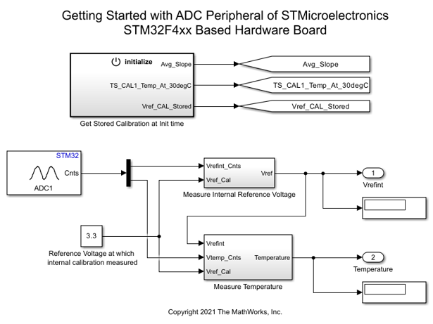
Using this model you can read internal reference voltage and temperature (Internal channels) with the help of an Analog to Digital Converter block at every sample time step of the model.
Task 1 - Configure ADC Block in Simulink Modeling to Read Internal Reference Voltage and Temperature
In this task, the Analog to Digital Converter block is configured to output an array to two channels on NUCLEO-F429ZI board.
First element of the output is digitized voltage measured from the Reference Voltage channel.
Second element of the output is digitized voltage measured from the temperature.
1. Open the stm32_adc_gettingstarted target model.
2. Configure the blocks. Double-click the block to open the block parameter dialog box.
The ADC block in model is set with
Trigger and readto convert ADC every step of model in generated code.

3. Create a new STM32CubeMX project or browse to an existing STM32CubeMX project. Launch the STM32CubeMX project in the STM32CubeMX tool. For details, see Getting Started with STMicroelectronics STM32 Processor Based Boards.
4. Perform the following configurations to enable and configure ADC1 channels to digitize Reference Voltage and Temperature:
On STM32F4x9 processor chips, reference voltage and temperature are mapped to analog channel 17 and analog channel 18.

Ensure that
End of Conversion Selectionis set to EOC flag at the end of all conversions.

Enable direct memory access (DMA) for ADC1 as it is sampling more than one channel and to ensure no data is missed. To enable DMA, follow following steps:

5. In your STM32CubeMX project, ensure to perform the following configurations:
Enable Do not generate the main() under Project Manager > Project.
Disable Generate under root under Project Manager > Project.
Under Project Manager > Advanced Settings > Driver Selector, select low level (LL) drivers for the peripherals.
Under Project Manager > Advanced Settings > Generate Functions Calls, deselect Do Not Generate Function Calls for all the peripheral initialization function calls.
Under Project Manager > Advanced Settings > Generate Function Calls, deselect Visibility (Static) for all the peripheral initialization function calls.
Save the project.
Monitor and Tune the Model
When you perform Monitor & Tune action for the model, the host computer communicates with the target, on which the generated executable runs.
1. Open the Hardware tab and click Monitor & Tune. You can observe from the Diagnostic Viewer that the code is generated for the model and the host connects to the target after loading the generated executable.

2. While the model is running, observe the Display block to view digitized signals in real time.
Task 2 - Configure ADC Trigger from External Source
In this task, configure the Analog To Digital Converter (ADC) to be triggered by external event to measure internal reference voltage and temperature (Internal channels).
The external event generation to trigger an ADC is controlled by the model.
1. Open the stm32_adc_ext_trig_gettingstarted target model.
2. Create a new STM32CubeMX project or browse to an existing STM32CubeMX project. Launch the STM32CubeMX project in the STM32CubeMX tool. For details, see Getting Started with STMicroelectronics STM32 Processor Based Boards.
3. Configure ADC1 to start conversions from an external events:
Select pin 11 of GPIOE port (PE11) to generate event on EXTI 11 line whenever a positive edge is detected on the PE11 pin.
To generate events on EXTI 11 line, the Simulink model is expecting pin PE11 to be connected to pin 10 of GPIOE port (PE10). Hence, pin PE10 must be configured as GPIO_Output in your STM32CubeMX project.

4. In your STM32CubeMX project, ensure you perform the following configurations:
Enable Do not generate the main() under Project Manager > Project.
Disable Generate under root under Project Manager > Project.
Under Project Manager > Advanced Settings > Driver Selector, select low level (LL) drivers for the peripherals.
Under Project Manager > Advanced Settings > Generate Functions Calls, deselect Do Not Generate Function Calls for all the peripheral initialization function calls.
Under Project Manager > Advanced Settings > Generate Function Calls, deselect Visibility (Static) for all the peripheral initialization function calls.
Save the project.
5. Configure the blocks. Double-click the block to open the block parameter dialog box.
Configure Analog to Digital Converter block to Read results only trigger mode as ADC1 is configured to start conversion on external event source.
Since, ADC is configured to trigger based on external event, the ADC conversions are read in DMA2_Stream 0 transfer complete interrupt to capture as and when conversions are ready.

Configure GPIOE block to pin 10.

Generate Code and Load on Hardware Board from Simulink Model
Monitor and Tune the Model
When you perform Monitor & Tune action for the model, the host computer communicates with the target, on which the generated executable runs.
1. Open the Hardware tab and click Monitor & Tune. You can observe from the Diagnostic Viewer that the code is generated for the model and the host connects to the target after loading the generated executable.

2. While the model is running, observe the Display block to view digitized signals in real time.
Other Things to Try
Try running the example to read the temperature when Analog to Digital Converter block is set to Injected conversion group.