Implement Symbolic Dimensions for Array Sizes in Generated Code
Symbolic dimensions enable the use of symbols instead of fixed numerical values for dimensions during model development. Wherever you need to specify a signal dimension in the model, you can use symbolic dimensions instead of actual numbers, which provides flexibility for changing the dimensions. For more information, see Use Symbolic Signal Dimensions.
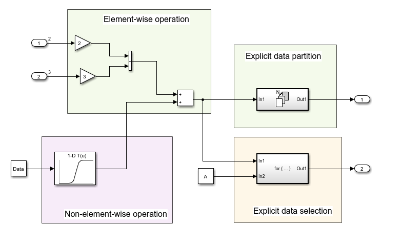
This example shows how to implement symbolic dimensions in the model DimensionVariants, which has four modeling patterns involving vectors and matrices, and to generate code with CompilerFlag and ImportedDefine storage classes.
To view block names, in the Debug tab, select Information Overlays and clear Hide Automatic Block Names.
Open the Embedded Coder app. In the C Code tab, select Code Interface > Individual Element Code Mappings. In the Code Mappings editor, under the Parameters tab, click Refresh. Seven Simulink.Parameter objects appear, four of which specify symbolic dimensions: A, B, C, and D. These parameters have a storage class of CompilerFlag.
Specify Symbolic Dimensions for Blocks and Data Objects
In the Simulink Toolstrip, on the Modeling tab, select Property Inspector from the Design gallery.
Click Inport Block
In1. In the Property Inspector, the Port Dimensions property is set to theSimulink.ParameterobjectA.Click Inport block
In2. The Port Dimensions property is set to theSimulink.ParameterobjectB.Click the Constant block. The Constant value property is set to the
Simulink.ParameterobjectData.In the Code Mappings editor, on the Parameters tab, click the
Simulink.ParameterobjectData. The Dimension field has the character vector'[1,C]', which is equivalent to'[1,5]'becauseChas a value of5. The Value property contains a 1-by-5 array, consistent with its dimensions. The dimensions of the data object must be consistent with the value of theSimulink.Parameterobject that is in the Dimensions field.Datahas a Storage class ofImportedExtern.Open the
1-D Lookup Table1Block parameters dialog box. The Table data parameter is set toSimulink.ParameterPT. The Breakpoints 1 field contains theSimulink.ParameterPB.In the Code Mappings editor, click
PBandPTand view their properties. These parameters have the Dimensions property set to'[1,D]'and are 1-by-15 arrays, consistent withD's value of15.
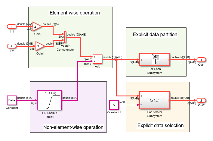
Simulate the model. Simulink propagates the dimensions symbolically in the diagram.
Generate Code
After verifying dimension specifications through model simulation, generate code for DimensionVariants.
Build the model.
model = "DimensionVariants";
slbuild(model);
### Searching for referenced models in model 'DimensionVariants'. ### Total of 1 models to build. ### Starting build procedure for: DimensionVariants ### Successful completion of build procedure for: DimensionVariants Build Summary Top model targets: Model Build Reason Status Build Duration ==================================================================================================================== DimensionVariants Information cache folder or artifacts were missing. Code generated and compiled. 0h 0m 9.6741s 1 of 1 models built (0 models already up to date) Build duration: 0h 0m 10.089s
View the generated code. In the DimensionVariants.h file, symbolic dimensions are in data declarations.
hfile = fullfile('DimensionVariants_ert_rtw',...
    'DimensionVariants.h');
coder.example.extractLines(hfile,'/* External inputs', '/* Real-time', 1, 0);
/* External inputs (root inport signals with default storage) */
typedef struct {
  real_T In1[A];                       /* '<Root>/In1' */
  real_T In2[B];                       /* '<Root>/In2' */
} ExtU;

/* External outputs (root outports fed by signals with default storage) */
typedef struct {
  real_T Out1[(A + B)];                /* '<Root>/Out1' */
  real_T Out2[(A + B)];                /* '<Root>/Out2' */
} ExtY;
Symbolic dimensions are defined as macros in the header files.
hfile = fullfile('DimensionVariants_ert_rtw',...
    'DimensionVariants.h');
coder.example.extractLines(hfile,'#ifndef A', '* Constraints for division operations', 1, 0);
#ifndef A
#error The value of parameter "A" is not defined
#endif

#ifndef B
#error The value of parameter "B" is not defined
#endif

#ifndef C
#error The value of parameter "C" is not defined
#endif

#ifndef D
#error The value of parameter "D" is not defined
#endif

/*
The DimensionVariants.h file contains data definitions and preprocessor conditionals that define constraints established among the symbols during simulation. One of these constraints is that the value of a symbolic dimension must be greater than 1.
hfile = fullfile('DimensionVariants_ert_rtw',...
    'DimensionVariants.h');
coder.example.extractLines(hfile,'#if A <= 1', '/* Macros for accessing', 1, 0);
#if A <= 1
# error "The preprocessor definition 'A' must be greater than '1'"
#endif

#if B <= 1
# error "The preprocessor definition 'B' must be greater than '1'"
#endif

/* Constraint 'D > 1' registered by:
 * '<Root>/1-D Lookup Table1'
 */
#if D <= 1
# error "The preprocessor definition 'D' must be greater than '1'"
#endif

/* Constraint 'C > 3' registered by:
 * '<S2>/Assignment'
 */
#if C <= 3
# error "The preprocessor definition 'C' must be greater than '3'"
#endif

#if A >= 11
# error "The preprocessor definition 'A' must be less than '11'"
#endif

#if B >= 11
# error "The preprocessor definition 'B' must be less than '11'"
#endif

/* Constraint 'D < 21' registered by:
 * '<Root>/1-D Lookup Table1'
 */
#if D >= 21
# error "The preprocessor definition 'D' must be less than '21'"
#endif

/* Constraint 'C < 11' registered by:
 * '<S2>/Assignment'
 */
#if C >= 11
# error "The preprocessor definition 'C' must be less than '11'"
#endif
DimensionVariants.h file also includes the user-provided header file for any Simulink.Parameter objects with an ImportedDefine custom storage class.
In the DimensionVariants.c file, symbolic dimensions are used in loop bound calculations, array size and index offset calculations, and a parameterized utility function (such as a Lookup Table block) calculation.
cfile = fullfile('DimensionVariants_ert_rtw',...
    'DimensionVariants.c');
coder.example.extractLines(cfile,'/* Model step', '/* Model initialize', 1, 0);
/* Model step function */
void DimensionVariants_step(void)
{
  real_T rtb_VectorConcatenate[A + B];
  real_T rtb_VectorConcatenate_0;
  int32_T ForEach_itr;
  int32_T i;
  int32_T s2_iter;

  /* Gain: '<Root>/Gain' incorporates:
   *  Inport: '<Root>/In1'
   */
  for (ForEach_itr = 0; ForEach_itr < A; ForEach_itr++) {
    rtb_VectorConcatenate[ForEach_itr] = 2.0 * rtU.In1[ForEach_itr];
  }

  /* End of Gain: '<Root>/Gain' */

  /* Gain: '<Root>/Gain1' incorporates:
   *  Inport: '<Root>/In2'
   */
  for (ForEach_itr = 0; ForEach_itr < B; ForEach_itr++) {
    rtb_VectorConcatenate[A + ForEach_itr] = 3.0 * rtU.In2[ForEach_itr];
  }

  /* End of Gain: '<Root>/Gain1' */

  /* Outputs for Iterator SubSystem: '<Root>/For Each Subsystem' incorporates:
   *  ForEach: '<S1>/For Each'
   */
  for (ForEach_itr = 0; ForEach_itr < (A + B); ForEach_itr++) {
    /* Sum: '<Root>/Add' incorporates:
     *  Constant: '<Root>/Constant'
     *  Lookup_n-D: '<Root>/1-D Lookup Table1'
     */
    rtb_VectorConcatenate_0 = look1_binlx(Data[ForEach_itr], PB, PT, (uint32_T)
      ((int32_T)(D - (int32_T)1))) + rtb_VectorConcatenate[ForEach_itr];
    rtb_VectorConcatenate[ForEach_itr] = rtb_VectorConcatenate_0;

    /* ForEachSliceAssignment generated from: '<S1>/Out1' incorporates:
     *  ForEachSliceSelector generated from: '<S1>/In1'
     *  MATLAB Function: '<S1>/MATLAB Function'
     */
    /* MATLAB Function 'For Each Subsystem/MATLAB Function': '<S3>:1' */
    /* '<S3>:1:4' y = 2*u; */
    rtY.Out1[ForEach_itr] = 2.0 * rtb_VectorConcatenate_0;
  }

  /* End of Outputs for SubSystem: '<Root>/For Each Subsystem' */

  /* Outputs for Iterator SubSystem: '<Root>/For Iterator Subsystem' incorporates:
   *  ForIterator: '<S2>/For Iterator'
   */
  /* Constant: '<Root>/Constant1' */
  ForEach_itr = ((int32_T)A);
  if (((int32_T)A) < (int8_T)0) {
    ForEach_itr = 0;
  }

  /* End of Constant: '<Root>/Constant1' */
  for (s2_iter = 0; s2_iter < ForEach_itr; s2_iter++) {
    /* Assignment: '<S2>/Assignment' incorporates:
     *  Constant: '<S2>/Constant'
     *  Outport: '<Root>/Out2'
     *  Product: '<S2>/Product'
     *  Selector: '<S2>/Selector'
     */
    if (s2_iter == (int8_T)0) {
      for (i = 0; i < (A + B); i++) {
        rtY.Out2[i] = rtb_VectorConcatenate[i];
      }
    }

    rtY.Out2[s2_iter] = rtb_VectorConcatenate[s2_iter] * 2.0;

    /* End of Assignment: '<S2>/Assignment' */
  }

  /* End of Outputs for SubSystem: '<Root>/For Iterator Subsystem' */
}
You must fix symbolic dimension values at compile-time. You can not resolve a symbolic dimension to another variable and then vary it during run-time because you define the behavior during simulation.
Set Parameter Value Based on Variant Choice
When you specify the dimensions of a parameter in a model by using a symbol, you must ensure that the parameter value aligns with the dimension value. To simulate different choices for the dimension value, manually correct the parameter value.
For example, in the DimensionVariants model, the Simulink.Parameter object Data stores a vector value [1 2 3 4 5] and uses a symbolic dimension C with initial value 5. If you change the value of C, to simulate the model, make sure that the length of the vector matches the new value of C.
To reduce the effort of maintenance when you change the value of C, you can set the value of Data to an expression involving C.
In the MATLAB code syntax, the value of Data is [1:C]. To preserve this relationship between the parameter objects, set the value of Data by using the slexpr function.
Data.Value = slexpr('1:C')
For more complicated applications, you can write your own MATLAB function that returns parameter values based on symbolic dimensions. Set the value of the parameter Data to an expression that calls your function. For general information about using an expression to set the value of a Simulink.Parameter object, see Set Variable Value by Using a Mathematical Expression.
Tip:
You must provide the initialization code for Simulink.Parameter objects that contain symbolic dimensions. To prevent the generated code from initializing these parameters, you must either:
Configure the parameters to use a storage class with the Data scope property set to
Imported, such as theImportedExternorImportedExternPointerbuilt-in storage classes.Configure the parameters to use a storage class with the Data initialization property set to
None.