Generate Code for Model References Connected to Variant Blocks
This example shows how to use Model blocks with variant blocks to reuse and incrementally load, build, and generate code for multiple variations of a component.
When you generate code for a referenced model hierarchy, the code generator places the code for the top model in the code generation folder and the code for referenced models in an slprj folder. Within the slprj folder, the subfolders further categorize the generated code by each referenced model and by file type, such as source code, header files, and other necessary files for compilation.
If you have an Embedded Coder® license, custom targets must declare themselves as compliant with the referenced model if they support Model blocks. For more information, see Support Model Referencing.
To get started with an example on how to generate code for a referenced model, see Generate Code for Model Reference Hierarchy.
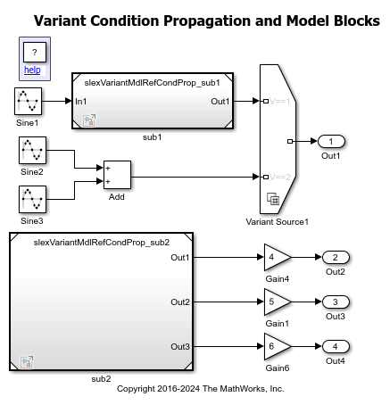
Explore the Model
Open the slexVariantMdlRefCondProp model from the Propagate Variant Conditions to Enable or Disable Model or Subsystem References in Hierarchy example.
This model contains two Model blocks sub1 and sub2. The sub1 block references the model slexVariantMdlRefCondProp_sub1 and serves as an input to the Variant Source1 block. The sub2 block references the model slexVariantMdlRefCondProp_sub2. The output of sub2 is determined by the variant conditions for the Variant Sink block in the slexVariantMdlRefCondProp_sub2 model.
The variant conditions at the input and the output ports of the Variant Source and Variant Sink blocks determine the activation and deactivation of connected blocks. In this model, the Variant Source1 block has a variant condition V == 1 that propagates to the Model block sub1 during simulation. Here, V is a scalar MATLAB™ variant control variable. You can specify V as a different type of variant control variable based on your requirements as described in Types of Variant Control Variables (Operands) in Variant Blocks.
If sub1 is active, the blocks within sub1 are also active. If sub1 is inactive, the blocks within sub1 are also inactive, making sub1 conditional.
You can also convert a subsystem to a referenced model. For more details, see Convert Subsystems to Referenced Models.
model = "slexVariantMdlRefCondProp";
open_system(model);
Specify the value of V as 1. Simulate the model to observe the active and inactive variant choices.
V = 1;
sim(model);
Configure Model to Generate Code with Preprocessor #if Conditionals
By default, Simulink® supports generating code only for a specific choice of a variant block. You can customize your model to generate code for multiple choices of the block by using the Variant activation time parameter. The different choices are guarded by preprocessor conditional statements #if by using the Variant activation time parameter. These conditional statements enable you to conditionally compile the code to selectively include or exclude code based on the variant condition that evaluates to true. You are not required to regenerate code each time the value of the variant control variable changes. Additionally, this approach allows to analyze variant choices for potential incompatibilities, such as data type and dimension mismatches, prior to simulation and code generation. For more information, see Activate Variant During Different Stages of Simulation and Code Generation Workflow.
To generate code with preprocessor conditionals #if and #elif, you must have an Embedded Coder license and the model must specify an ERT-based system target file, for example, ert.tlc. You must also set the Variant activation time parameter of the Variant Source1 and Variant Sink blocks to code compile.
1. In the Apps tab of the toolstrip, navigate to Embedded Coder. For detailed information on the settings to generate code, see Generate Code Using Embedded Coder.
2. In the C code tab, select Build > Generate code. The code generator generates code for the top model and a library module called a model reference target for each referenced model. The code for the top model is placed in the code generation folder and the code for referenced models is placed in an slprj folder.
slexVariantMdlRefCondProp_ert_rtw- The build folder containing the generated code for the top model.
slprj>ert>slexVariantMdlRefCondProp_sub1andslprj>ert>slexVariantMdlRefCondProp_sub2- The folders containing the generated code for the referenced models.
slexVariantMdlRefCondProp.slxc- The Simulink cache file for the top model.
slexVariantMdlRefCondProp_sub1.slxcandslexVariantMdlRefCondProp_sub2.slxc- The Simulink cache files for the referenced models.
slbuild(model);
### Searching for referenced models in model 'slexVariantMdlRefCondProp'.
### Total of 3 models to build.
### Starting serial code generation build.
### Starting build procedure for: slexVariantMdlRefCondProp_sub1
### Successful completion of build procedure for: slexVariantMdlRefCondProp_sub1
### Starting build procedure for: slexVariantMdlRefCondProp_sub2
### Successful completion of build procedure for: slexVariantMdlRefCondProp_sub2
### Starting build procedure for: slexVariantMdlRefCondProp
### Successful completion of build procedure for: slexVariantMdlRefCondProp

Build Summary

Model reference code generation targets:

Model                           Build Reason                                              Status                        Build Duration
======================================================================================================================================
slexVariantMdlRefCondProp_sub1  Target (slexVariantMdlRefCondProp_sub1.c) did not exist.  Code generated and compiled.  0h 0m 5.1512s
slexVariantMdlRefCondProp_sub2  Target (slexVariantMdlRefCondProp_sub2.c) did not exist.  Code generated and compiled.  0h 0m 3.5248s

Top model targets:

Model                      Build Reason                                         Status                        Build Duration
============================================================================================================================
slexVariantMdlRefCondProp  Information cache folder or artifacts were missing.  Code generated and compiled.  0h 0m 8.2079s

3 of 3 models built (0 models already up to date)
Build duration: 0h 0m 17.937s
3.Open the slexVariantMdlRefCondProp.c file. The header files and instances referring to the Model blocks are guarded in preprocessor conditionals #if and #elif. The preprocessor conditionals enable you to conditionally compile the code based on the variant conditions that evaluate to true. For more information, see Compile Code Conditionally for Variations of Component Represented Using Variant Block.
cfile=fullfile(pwd, "slexVariantMdlRefCondProp_ert_rtw", "slexVariantMdlRefCondProp.c");
coder.example.extractLines(cfile, "#include ""slexVariantMdlRefCondProp.h""", "#endif", 1, 0);
coder.example.extractLines(cfile, '/* Model step', '/* Model initialize', 1, 0);
#include "slexVariantMdlRefCondProp.h"
#include <math.h>
#include "rtwtypes.h"
#include <string.h>
#include "slexVariantMdlRefCondProp_sub2.h"
#if V == 1
#include "slexVariantMdlRefCondProp_sub1.h"

/* Model step function */
void slexVariantMdlRefCondProp_step(void)
{
  real_T rtb_sub2_o1;
  real_T rtb_sub2_o2;
  real_T rtb_sub2_o3;

  /* Sin: '<Root>/Sine1' incorporates:
   *  ModelReference: '<Root>/sub1'
   *  Sin: '<Root>/Sine2'
   *  Sin: '<Root>/Sine3'
   *  Sum: '<Root>/Add'
   */
#if V == 1

  rtb_sub2_o2 = sin(((real_T)slexVariantMdlRefCondProp_DW.counter +
                     slexVariantMdlRefCondProp_P.Sine1_Offset) * 2.0 *
                    3.1415926535897931 /
                    slexVariantMdlRefCondProp_P.Sine1_NumSamp) *
    slexVariantMdlRefCondProp_P.Sine1_Amp +
    slexVariantMdlRefCondProp_P.Sine1_Bias;
  slexVariantMdlRefCondProp_sub1(&rtb_sub2_o2, &slexVariantMdlRefCondProp_Y.Out1);

#elif V == 2

  /* Sin: '<Root>/Sine2' */
  rtb_sub2_o2 = sin(((real_T)slexVariantMdlRefCondProp_DW.counter_i +
                     slexVariantMdlRefCondProp_P.Sine2_Offset) * 2.0 *
                    3.1415926535897931 /
                    slexVariantMdlRefCondProp_P.Sine2_NumSamp) *
    slexVariantMdlRefCondProp_P.Sine2_Amp +
    slexVariantMdlRefCondProp_P.Sine2_Bias;

  /* Sin: '<Root>/Sine3' */
  rtb_sub2_o1 = sin(((real_T)slexVariantMdlRefCondProp_DW.counter_f +
                     slexVariantMdlRefCondProp_P.Sine3_Offset) * 2.0 *
                    3.1415926535897931 /
                    slexVariantMdlRefCondProp_P.Sine3_NumSamp) *
    slexVariantMdlRefCondProp_P.Sine3_Amp +
    slexVariantMdlRefCondProp_P.Sine3_Bias;

  /* VariantMerge generated from: '<Root>/Variant Source1' incorporates:
   *  Sum: '<Root>/Add'
   */
  slexVariantMdlRefCondProp_Y.Out1 = rtb_sub2_o2 + rtb_sub2_o1;

#endif

  /* End of Sin: '<Root>/Sine1' */

  /* ModelReference: '<Root>/sub2' */
  slexVariantMdlRefCondProp_sub2(&rtb_sub2_o1, &rtb_sub2_o2, &rtb_sub2_o3,
    &(slexVariantMdlRefCondProp_DW.sub2_InstanceData.rtdw));

  /* Outport: '<Root>/Out2' incorporates:
   *  Gain: '<Root>/Gain4'
   */
  slexVariantMdlRefCondProp_Y.Out2 = slexVariantMdlRefCondProp_P.Gain4_Gain *
    rtb_sub2_o1;

  /* Gain: '<Root>/Gain1' incorporates:
   *  Gain: '<Root>/Gain6'
   *  Outport: '<Root>/Out3'
   *  Outport: '<Root>/Out4'
   *  Sin: '<Root>/Sine1'
   *  Sin: '<Root>/Sine2'
   *  Sin: '<Root>/Sine3'
   */
#if V == 3

  slexVariantMdlRefCondProp_Y.Out3 = slexVariantMdlRefCondProp_P.Gain1_Gain *
    rtb_sub2_o2;

#elif V == 4

  /* Outport: '<Root>/Out4' incorporates:
   *  Gain: '<Root>/Gain6'
   */
  slexVariantMdlRefCondProp_Y.Out4 = slexVariantMdlRefCondProp_P.Gain6_Gain *
    rtb_sub2_o3;

#elif V == 1

  /* Update for Sin: '<Root>/Sine1' */
  slexVariantMdlRefCondProp_DW.counter++;
  if (slexVariantMdlRefCondProp_DW.counter ==
      slexVariantMdlRefCondProp_P.Sine1_NumSamp) {
    slexVariantMdlRefCondProp_DW.counter = 0;
  }

#elif V == 2

  /* Update for Sin: '<Root>/Sine2' */
  slexVariantMdlRefCondProp_DW.counter_i++;
  if (slexVariantMdlRefCondProp_DW.counter_i ==
      slexVariantMdlRefCondProp_P.Sine2_NumSamp) {
    slexVariantMdlRefCondProp_DW.counter_i = 0;
  }

  /* Update for Sin: '<Root>/Sine3' */
  slexVariantMdlRefCondProp_DW.counter_f++;
  if (slexVariantMdlRefCondProp_DW.counter_f ==
      slexVariantMdlRefCondProp_P.Sine3_NumSamp) {
    slexVariantMdlRefCondProp_DW.counter_f = 0;
  }

#endif

  /* End of Gain: '<Root>/Gain1' */
}
Configure Model to Generate Code with if Conditions
You can customize your model to generate code for multiple variant choices guarded by if and else if conditional statements in the generated code. These conditions enable code execution to selectively include or exclude startup routines based on variant conditions that evaluate to true during execution. You are not required to recompile the code each time the value of the variant control variable changes. Additionally, this approach allows you to analyze variant choices for potential incompatibilities, such as data type and dimension mismatches, prior to simulation and code generation. For more information, see Activate Variant During Different Stages of Simulation and Code Generation Workflow.
To generate code with if conditional statements to choose between variants make sure that the Variant activation time parameter in both the Variant Source1 and Variant Sink blocks is set to startup.
set_param(model+"/Variant Source1","VariantActivationTime","startup");
set_param(model+"_sub2/Variant Sink","VariantActivationTime","startup");
1. In the Apps tab of the toolstrip, navigate to Simulink Coder. For detailed information on the settings to generate code, see Generate Code Using Simulink Coder.
2. In the C code tab, select Build > Generate code.
The code generator produces a standalone executable for the top model and a library module called a model reference target for each referenced model. The code for the top model is placed in the code generation folder and the code for referenced models is placed in an slprj folder. The subfolders in slprj are separate places for different types of files. For folder information, see Manage Build Process Folders.
slexVariantMdlRefCondProp_grt_rtw- The build folder containing the generated code for the top model.
slprj>grt>slexVariantMdlRefCondProp_sub1andslprj>grt>slexVariantMdlRefCondProp_sub2- The folders containing the generated code for the referenced models.
slexVariantMdlRefCondProp.exe- The executable created by the build process.
slexVariantMdlRefCondProp.slxc- The Simulink cache file for the top model.
slexVariantMdlRefCondProp_sub1.slxcandslexVariantMdlRefCondProp_sub2.slxc- The Simulink cache files for the referenced models.
3.The header files contain the necessary declarations and definitions for all variant choices. Since the code generator cannot determine which variant will be used at compile time, these header files are not guarded. They are included in their entirety to support any variant choice that might be chosen at startup.
However, The instances referring to the Model blocks are guarded in if conditional statements. These if statements enable you to conditionally execute startup routines based on the variant condition that evaluates to true. For more information, see Run Executables for Variant Blocks Without Recompiling Code for Changing Active Choices Using Startup Activation Time.
Note
When the Variant activation time for a variant block is set to update diagram or update diagram analyze all choices, references to Model blocks connected to inactive variant choices are not included in the generated code.
See Also
Topics
Select a Web Site
Choose a web site to get translated content where available and see local events and offers. Based on your location, we recommend that you select: United States.
You can also select a web site from the following list
Americas
- América Latina (Español)
- Canada (English)
- United States (English)
Europe
- Belgium (English)
- Denmark (English)
- Deutschland (Deutsch)
- España (Español)
- Finland (English)
- France (Français)
- Ireland (English)
- Italia (Italiano)
- Luxembourg (English)
- Netherlands (English)
- Norway (English)
- Österreich (Deutsch)
- Portugal (English)
- Sweden (English)
- Switzerland
- United Kingdom (English)