Generate Multicycle Path Constraints for Multirate Models
A multicycle path is a data path between two sequential elements, such as registers or flip-flops, that takes multiple clock cycles to transfer data from the source register to the destination register. In HDL Coder™ designs, multicycle paths typically occur in multirate models that run in single-clock mode, where clock-enable signals control the slow-rate regions. Because these enables toggle at a fraction of the base clock frequency, the logic of these slow-rate regions spans several clock cycles. You can use the multicycle path (MCP) constraints to relax timing requirements for data paths that span multiple clock cycles. You can inform synthesis tools that certain register-to-register paths can take multiple cycles to propagate data by using multicycle path (MCP) constraints. For more information on how to generate MCP constraints, see Enable-Based Multicycle Path Constraints.
Sources of Multicycle Paths
HDL Coder generates multicycle path constraints based on the rate and phase of clock-enable signals from these blocks and optimizations:
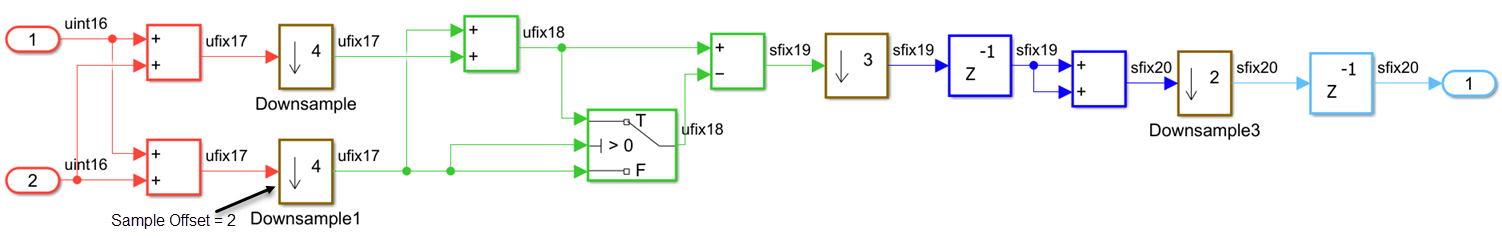
Blocks such as the Rate Transition, Downsample, and Upsample blocks introduce multiple sample times, which creates regions that operate at slower or faster rates than the base clock.
Multirate filter blocks, including CIC interpolation and decimation filters, contribute to varying rates.
Discrete-Time blocks that have custom sample times, such as filters, delays, or constant blocks also create multirate regions that require separate enable signals.
Blocks that apply an offset to sampling, such as Downsample or Upsample blocks that have a sample offset.
HDL Coder optimizations, such as oversampling, resource sharing, and pipelining, that insert pipeline registers or introduce multiple rates.
When you generate a multicycle path constraint, HDL Coder considers these blocks and optimizations when determining the setup and hold multipliers.
For more information the multirate models, see Code Generation from Multirate Models.
Setup and Hold Time for Slower Paths
When you apply multicycle path constraints, the synthesis tools relax the default single-cycle timing checks by the shifting setup and hold edges. These checks ensure that data launched from a source register is captured correctly at the destination register without timing violations.
Setup time — Defines how many clock cycles after the launch edge the data must be stable before the capture edge occurs.
Hold time — Specifies for how many cycles the data remains stable after the launch edge to avoid being overwritten before capture.
The synthesis tools use the setup and hold edges to synchronize the timing between the destination register and the data launched from the source register.
This figure shows the timing relationship between a source clock and a destination clock and illustrates how the synthesis tools apply the setup and hold checks.
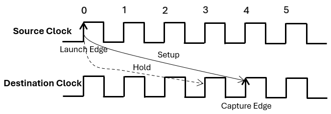
If a multicycle path requires four clock cycles to propagate data from the source register to the destination register, HDL Coder shifts the setup check by a multiplier of four and the hold check by one less than the setup multiplier in the generated MCP constraints.
set_multicycle_path 4 -setup -from <source_register> -to <destination_register>
set_multicycle_path 3 -hold -from <source_register> -to <destination_register>
The enable-based MCP constraints calculates setup and hold multipliers for the multicycle path based on the rate divisor, N, and the phase difference, Δ:
N is the greatest common divisor of the source register rate, NS and the destination register rate, ND.
N = GCD(NS, ND)
The checks compute the phase difference, Δ, from the source register phase, PS, and destination register phase, ND by using the equation:
Δ = (PS — PD) mod N
The checks calculate the setup and hold multipliers are calculated as:
The setup multiplier = N — Δ
The hold multiplier = (N — Δ ) — 1
If the hold multiplier is less than 1, the checks do not generate constraints for that multicycle path.
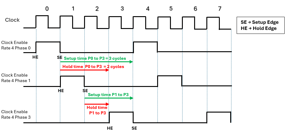
This figure shows the timing relationship between a clock signal and three clock-enable signals operating at the same rate but with different phase offsets. Each enable signal activates periodically based on its phase alignment with the base clock. The figure shows how to calculate setup and hold times for multicycle path constraints between registers gated by different phase enables.
Setup time is the number of cycles between the launch edge (SE of source phase) and the capture edge (SE of destination phase).
Hold time is one cycle less than setup time, between the launch edge and the hold edge.
Attributes and MCP Constructs Used in Enable-Based Constraints
HDL Coder inserts specific synthesis attributes into the generated HDL code to preserve timing controller logic and enable robust multicycle path (MCP) constraint generation. These attributes ensure that enable signals and phase registers remain identifiable after synthesis optimizations. The enable-based constraints uses these attributes:
| Attribute | Purpose | Applied To | HDL Code Example |
|---|---|---|---|
direct_enable | Prevents synthesis tools from optimizing away enable signals that control slow-rate regions. | All timing-controller enable signals | VHDL: ATTRIBUTE direct_enable OF enb_1_6_1 : SIGNAL IS "yes"; Verilog: (* direct_enable = "yes" *) output enb_1_6_1; |
keep | Preserves phase registers during synthesis so they are not absorbed into other logic. | Phase registers (e.g., phase_0, phase_1) | VHDL: ATTRIBUTE keep OF phase_0 : SIGNAL IS "true"; Verilog: (* keep = "true" *) wire phase_0; |
mcp_info | Tags phase registers with a unique identifier for constraint scripts to locate enable-gated register groups. | Phase registers and enable domains | VHDL: ATTRIBUTE mcp_info OF phase_0 : SIGNAL IS "Subsystem_tc.u1_d150_o0"; Verilog: (* mcp_info = "Subsystem_tc.u1_d150_o0" *) wire phase_0; |
HDL Coder uses these constructs when creating the enable-based constraints for the Xilinx Vivado tool:
| Element | Purpose | Example Syntax |
Anchor Register (enbregcell) | Identifies the timing controller phase register that serves as the anchor for the enable group. |
set enbregcell [get_cells -hier -filter {mcp_info=="Subsystem_tc.u1_d150_o0"}] |
Enable Net (enbregnet) | Captures the net driven by the anchor register’s output pin, which fans out to all gated registers. |
set enbregnet [get_nets -of_objects [get_pins -of_objects $enbregcell -filter {DIRECTION == OUT}]] |
Register List (reglist) | Collects all flip-flops gated by the enable signal for
applying MCP constraints. Filters by
IS_ENABLE property. |
set reglist1 [get_cells -of [filter [all_fanout -flat -endpoints_only $enbregnet] IS_ENABLE]] |
| Setup Constraint | Specifies the number of cycles allowed for setup timing between source and destination registers. |
set_multicycle_path 150 -setup -from $reglist1 -to $reglist1 -quiet |
| Hold Constraint | Specifies the hold timing relaxation, always one cycle less than setup. |
set_multicycle_path 149 -hold -from $reglist1 -to $reglist1 -quiet |
-quiet
| Suppresses warnings or informational messages during constraint application. | Added at the end of set_multicycle_path
command. |
IS_ENABLE | Ensures only enable-gated registers are included in the register list. | Used in filter: filter [all_fanout -flat
-endpoints_only $enbregnet] IS_ENABLE |
Multicycle Path Constraints for Models with Different Rates and Phases
This example shows how to generate multicycle path (MCP) constraints for a model with multiple slower sample rates. It demonstrates MCP constraint generation for the Xilinx® Vivado® synthesis tool and explains how these constraints help you meet timing requirements.
Open Model
Open the MultirateMultiplePhases model. This model demonstrates a multirate design with three slower‑rate domains:
Rate 4: Four times slower than the base clock with phases {
0,1,3}.Rate 12: Twelve times slower than the base clock with phases{
0,1}.Rate 24: Twenty Four times slower than the base clock with phases{
0,1}.
load_system("MultirateMultiplePhases");
set_param("MultirateMultiplePhases",'SimulationCommand','update');
open_system("MultirateMultiplePhases/DUT");
Generate HDL Code and MCP Constraints
To generate the multicycle path constraints, open the Configuration Parameters settings, in the HDL Code Generation > Optimization > General tab, select Enable-based Constraints parameter. You can also use this hdlset_param command:
hdlset_param("MultirateMultiplePhases","MulticyclePathConstraints","on");
Generate the HDL code for the DUT subsystem in a model.
makehdl("MultirateMultiplePhases/DUT");### Working on the model MultirateMultiplePhases ### Generating HDL for MultirateMultiplePhases/DUT ### Using the config set for model MultirateMultiplePhases for HDL code generation parameters. ### Running HDL checks on the model 'MultirateMultiplePhases'. ### Begin compilation of the model 'MultirateMultiplePhases'... ### Working on the model 'MultirateMultiplePhases'... ### Working on... GenerateModel ### Begin model generation 'gm_MultirateMultiplePhases'... ### Copying DUT to the generated model.... ### Model generation complete. ### Generated model saved at hdl_prj/hdlsrc/MultirateMultiplePhases/gm_MultirateMultiplePhases.slx ### Begin Verilog Code Generation for 'MultirateMultiplePhases'. ### Begin Verilog Code Generation for 'DUT_tc'. ### Working on DUT_tc as hdl_prj/hdlsrc/MultirateMultiplePhases/DUT_tc.v. ### Code Generation for 'DUT_tc' completed. ### Working on MultirateMultiplePhases/DUT as hdl_prj/hdlsrc/MultirateMultiplePhases/DUT.v. ### Code Generation for 'MultirateMultiplePhases' completed. ### Generating HTML files for code generation report at index.html ### Writing Vivado multicycle constraints XDC file hdl_prj/hdlsrc/MultirateMultiplePhases/DUT_constraints.xdc ### Creating HDL Code Generation Check Report DUT_report.html ### HDL check for 'MultirateMultiplePhases' complete with 0 errors, 0 warnings, and 1 messages. ### HDL code generation complete.
In a multirate design, HDL Coder generates timing controller logic that manages clock-enable signals for slower rates. The timing controller produces clock-enable signals for each rate and phase. These enables gate registers in slower‑rate regions so they update only on valid cycles. The following code snippet shows the enable signals created for each rate and phase in DUT_tc.vhd.
// Master clock enable input: clk_enable
//
// enb_1_4_0   : 4x slower than clk with last phase
// enb_1_4_1   : 4x slower than clk with phase 1
// enb_1_4_3   : 4x slower than clk with phase 3
// enb_1_12_0  : 12x slower than clk with last phase
// enb_1_12_1  : 12x slower than clk with phase 1
// enb_1_24_0  : 24x slower than clk with last phase
// enb_1_24_1  : 24x slower than clk with phase 1
//
// -------------------------------------------------------------

`timescale 1 ns / 1 ns

module DUT_tc
          (clk,
           reset,
           clk_enable,
           enb_1_4_0,
           enb_1_4_1,
           enb_1_4_3,
           enb_1_12_0,
           enb_1_12_1,
           enb_1_24_0,
           enb_1_24_1);
...
These enable signals control registers in different rate regions and ensure they execute on the correct cycles. HDL Coder uses these signals to identify multicycle paths and generate MCP constraints for synthesis tools. It also applies synthesis attributes such as direct_enable, keep, and mcp_info to enable signals and phase registers to preserve them and make MCP generation robust. HDL Coder creates an XDC file named DUT_constraints.xdc for the DUT subsystem to relax timing requirements on multicycle paths. HDL Coder generates enable-based multicycle path constraints for slower-rate regions within these phase paths:
Same Rate Same Phase (Rate Divisor = Source Rate, Phase Difference () = 0). For example, this code snippet shows the multicycle path constraints for Rate 4 and Phase 0.
# Multicycle constraints for clock enable: DUT_tc.u1_d4_o0
set enbregcell [get_cells -hier -filter {mcp_info=="DUT_tc.u1_d4_o0"}]
set enbregnet [get_nets -of_objects [get_pins -of_objects $enbregcell -filter {DIRECTION == OUT}]]
set reglist1 [get_cells -of [filter [all_fanout -flat -endpoints_only $enbregnet] IS_ENABLE]]
set_multicycle_path 4 -setup -from $reglist1 -to $reglist1 -quiet
set_multicycle_path 3 -hold -from $reglist1 -to $reglist1 -quiet
Same Rate Different Phase (Rate Divisor = Source Rate, Phase Difference ). For example, this code snippet shows the multicycle path constraints between the Phase 0 and Phase 3 of Rate 4.
# Multicycle constraints from clock enable: DUT_tc.u1_d4_o0 to clock enable: DUT_tc.u1_d4_o3
set_multicycle_path 3 -setup -from $reglist1 -to $reglist3 -quiet
set_multicycle_path 2 -hold -from $reglist1 -to $reglist3 -quiet
Different Rate Same Phase (Rate Divisor = , Phase Difference () = 0). For example, this code snippet shows the multicycle path constraints between the Rate 4 Phase 0 and Rate 12 Phase 0.
# Multicycle constraints from clock enable: DUT_tc.u1_d4_o0 to clock enable: DUT_tc.u1_d12_o0
set_multicycle_path 4 -setup -from $reglist1 -to $reglist4 -quiet
set_multicycle_path 3 -hold -from $reglist1 -to $reglist4 -quiet
Different Rate Different Phase (Rate Divisor = , Phase Difference ). For example, this code snippet shows the multicycle path constraints between the Rate 24 Phase 1 and Rate 4 Phase 0.
# Multicycle constraints from clock enable: DUT_tc.u1_d24_o1 to clock enable: DUT_tc.u1_d4_o0
set_multicycle_path 3 -setup -from $reglist7 -to $reglist1 -quiet
set_multicycle_path 2 -hold -from $reglist7 -to $reglist1 -quiet
Perform Synthesis and Implementation
After you generate the HDL Code and MCP constraints, you can perform the synthesis of the model using HDL Workflow Advisor.
In the Simulink toolstrip, click Apps tab and select HDL Coder app. In the HDL Code tab, select the Workflow Advisor button.
Select the target device and synthesis tool.
In the FPGA Synthesis and Analysis > Perform Synthesis and P/R > Run Implementation task, clear Skip this task and click Apply. Then, right-click this task and select Run to Selected Task.
The task displays the amount of resources consumed by the design and the data path delay. The slack is the difference between the required time and the arrival time for a combination path.
See Also
Code Generation from Multirate Models | Enable-Based Multicycle Path Constraints