Get Started with HLS IP Core Generation Workflow
An IP core — or a semiconductor intellectual property core — is a reusable HDL component in FPGA, programmable system-on-chip (SoC), and ASIC design. This example shows how to use the HLS code generation workflow to generate a customized IP core that runs the FFT algorithm on the target hardware. This example deploys the generated IP core on the ZedBoard hardware.
You can use MATLAB® and HDL Coder™ to design, simulate, and verify your application; perform what-if scenarios with algorithms; and optimize parameters. Using this example, you can:
1. Set up your Zynq® hardware and tools.
2. Convert your MATLAB algorithm to an IP core using the HDL Coder MATLAB to HLS code generation workflow. This involves:
Converting the MATLAB algorithm to synthesizable C++ code using HDL Coder, followed by C synthesis using Xilinx® Vitis HLS.
Integrating the IP core with a predefined reference design and building the entire system in Vivado to generate a bitstream that can be deployed on the hardware.
3. Deploy the IP core to Zynq hardware.
Prerequisites
Install Xilinx Vivado® and Xilinx Vitis HLS.
Set the path to the installed Xilinx Vitis HLS tool for the target device using the
hdlsetuphlstoolpathfunction. In the MATLAB Command Window, use the following command, replacing the path with your installation path. This command also sets up the path for Vivado for the IP core workflow.
hdlsetuphlstoolpath("ToolName","Xilinx Vitis HLS","ToolPath","C:\Xilinx\Vitis\2024.1\bin");
HDL Coder Support Package for AMD FPGA and SoC Devices.
Set up the ZedBoard. For more information, see the section Set Up Zynq Hardware and Tools in Get Started with IP Core Generation from Simulink Model.
Create MATLAB HDL Coder Project
Using this example, you can deploy the mlhdlc_fft24 function on the target platform. This function performs an FFT of length 24 on hardware and returns the output data. The input x and output y are complex vectors which are mapped to the AXI4-Lite interface and are used to write or read data back to the processor.
Create an HDL Coder project by running this command in the MATLAB Command Window.
coder -hdlcoder -new ff24ipcore
Alternatively, in the Apps tab, click HDL Coder. In the HDL Code Generation pane:
Set the MATLAB Function to the locally saved MATLAB function,
mlhdlc_fft24.Set the MATLAB Test Bench to the locally saved MATLAB test bench,
mlhdlc_fft24_tb.In the MATLAB Function section, select Autodefine types to define the input types automatically.
Click Workflow Advisor.
Define Code Generation Target
You can generate a shareable and reusable IP core using the HDL Workflow Advisor. HDL Coder integration with the Xilinx Vivado IDE facilitates the incorporation of the generated IP core into the FPGA design.
Perform IP core generation using the MATLAB HDL Workflow Advisor:
In the MATLAB HDL Workflow Advisor, from the Code Generation Workflow list, select
MATLAB to HLS.Click Select Code Generation Target and set Workflow to
IP Core Generation.
Specify Platform
In order to integrate the generated IP core in a reference design, set Platform to one of these target platforms:
Generic Xilinx Platform — This is a board-independent option that generates a generic Xilinx IP core. However, you must manually integrate the IP core into an existing Xilinx Vivado project.
Board-specific platforms — The boards listed in the Platform are specific to Xilinx and you can integrate the IP core into a predefined reference design.
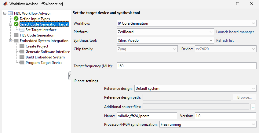
For this example, target the ZedBoard platform and set these parameters:
Set Platform to
ZedBoard.Set Synthesis tool to
Xilinx Vivado.Set Target Frequency (MHz) to 150.
Under IP core settings, set Reference design to
Default systemand Processor/FPGA synchronization toFree running(default).
For more information, see Processor and FPGA Synchronization.
Set the Interfaces
Use the Set Target Interface task to map each input and output in the MATLAB design function to AXI4-Lite or external interfaces of the IP Core target.
In the Ports tab, from the Target Platform Interfaces column, set the interface for x and y to the AXI4-Lite interface.
In the Set target interface step, when the I/O is mapped to a AXI4-Lite interface, the corresponding interface tcl directive is generated in the syn_script.tcl. You can click on the generated link to open syn_script.tcl. Right click the Set Target Interface subtask and click on Run to Selected Task.

Generate and Integrate IP Core with Xilinx Vivado Environment
To generate the IP core, right click the HLS Code generation task and select Run this task. In this step, synthesizable C++ code is generated from the MATLAB code and is synthesized to generate IP core using Xilinx Vitis HLS.
After generating the IP core, you can integrate it with a reference design, synthesize, and download the bitstream to the FPGA within the MATLAB HDL Workflow Advisor.
Create a Xilinx Vivado project and integrate the IP core in to a predefined reference design using the Create Project step under the Embedded System Integration task.
Right click the Generate Software Interface subtask and select Run This Task to generate
gs_mlhdlc_fft24_interface.mandgs_mlhdlc_fft24_setup.m. Use these files to verify your generated IP core on the ZedBoard hardware. These files contain commands that you can use to connect to your hardware and interact with the IP core. The interface and setup files are generated only if the selected Platform has processing system. You can skip the subtask if the Platform does not have processing system.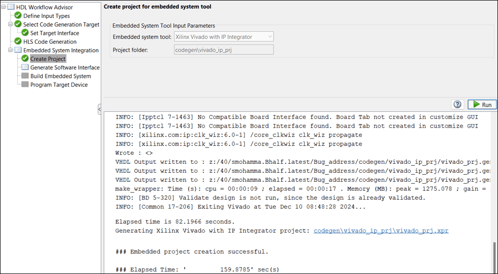
In the Build Embedded System subtask, select Run build process externally and then click Run. The Xilinx synthesis tool runs as a separate process outside of MATLAB. Wait for the synthesis tool to complete.
Once the bitstream generation is complete, right-click the Program Target Device subtask and select Run This Task to program the ZedBoard.
Run and Verify IP Core on the Hardware
Open the generated setup and interface files. For more information, see Generate and Manage FPGA I/O Host Interface Scripts.
The gs_mlhdlc_fft24_interface.m script establishes a connection to your hardware and uses the gs_mlhdlc_fft24_setup function to enable data reading and writing by configuring the fpga hardware object with the mapped ports and interfaces from the Set Target Interface subtask.
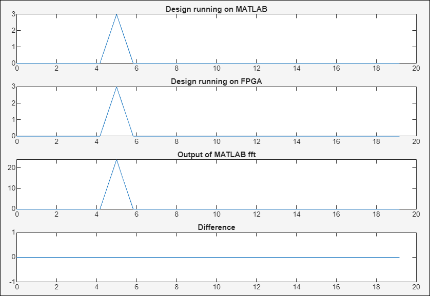
You can use these commands to read and write data to the mapped ports. The readPort and writePort are present in the gs_mlhdlc_fft24_interface.m. The plot shows that there is no difference in the MATLAB code and the code deployed on the hardware.
fs = 20;  % Sampling frequency
t = 0:1/fs:2*pi*10;
F = 5;
X = complex(cos(2*pi*F*t), sin(2*pi*F*t));
X_fi = fi(X(1:1200), 1, 18, 16);
frameSize = 24;
frame = X_fi(1:frameSize);
gs_mlhdlc_fft24_interface;
for ii=1:frameSize:numel(X_fi)
    frame(:) = X_fi(ii:ii+frameSize-1);
    writePort(hFPGA, "x", frame);
    MATLABDesignOut(ii:ii+frameSize-1) = mlhdlc_fft24(frame);
    HardwareOut(ii:ii+frameSize-1) = readPort(hFPGA, "y");
end

% Plot one frame to show sine wave at 5Hz
figure(1);
freqs = 0:fs/frameSize:(fs-fs/frameSize);

% mlhdlc_fft24 running on MATLAB
subplot(4,1,1),plot(freqs, abs(MATLABDesignOut(1:frameSize)));
title('Design running on MATLAB')

% mlhdlc_fft24 running on hardware
subplot(4,1,2),plot(freqs, abs(HardwareOut(1:frameSize)));
title('Design running on FPGA')

% compare with MATLAB fft
matlab_fft = fft(X(1:frameSize));
subplot(4,1,3),plot(freqs, abs(matlab_fft(1:frameSize)));
title('Output of MATLAB fft')

% plot difference
subplot(4,1,4),plot(freqs, abs(abs(MATLABDesignOut(1:frameSize))-abs(HardwareOut(1:frameSize))));
title('Difference')