RF Data Converter IQ Mixer Mode on RFSoC Device
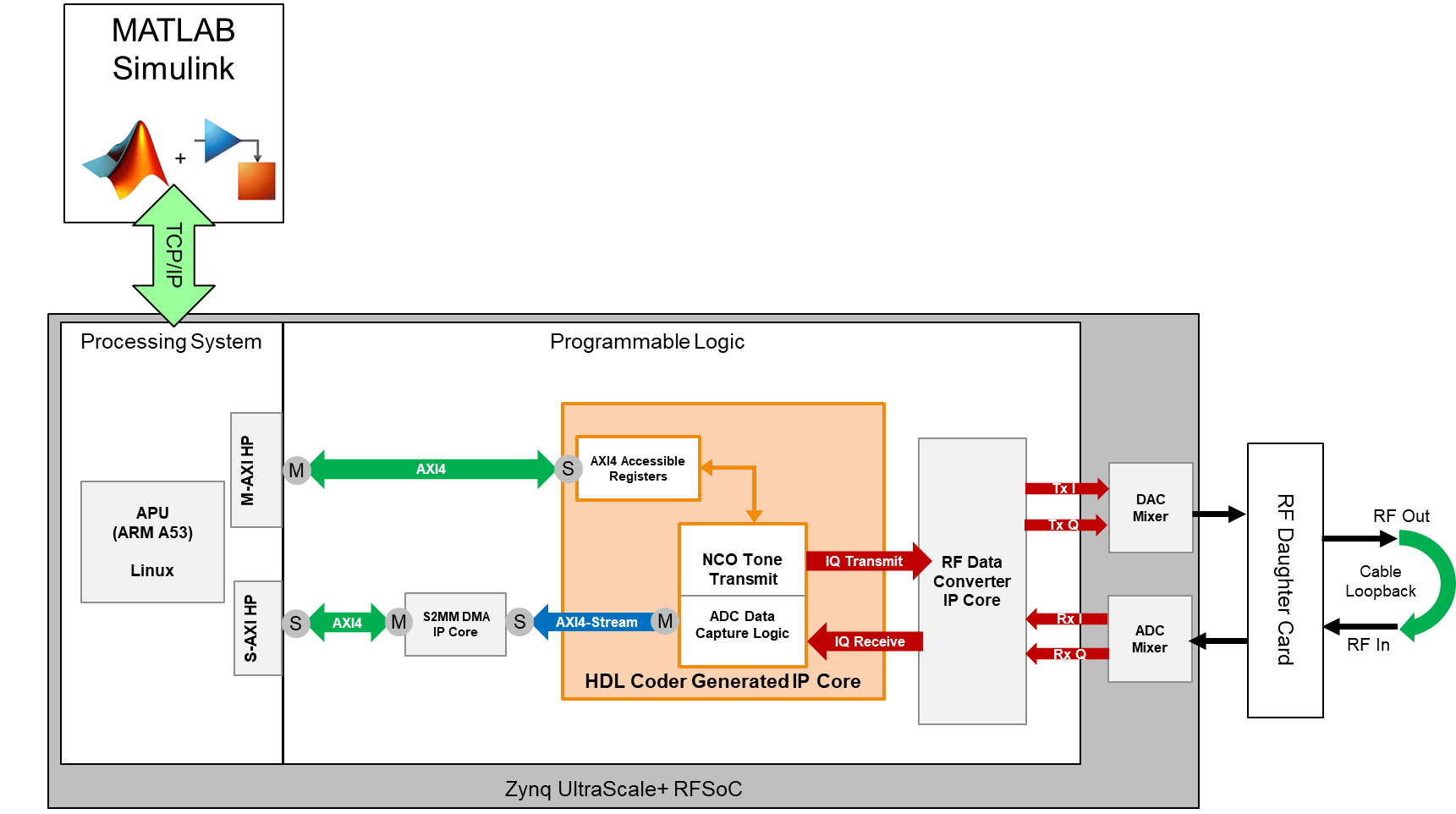
This example shows how to enable the RFSoC built-in numerically-controlled oscillator (NCO) mixer. The mixer design uses a different data format that, instead of providing real signals, provides a complex in-phase and quadrature (IQ) signal to a digital-to-analog converter (DAC) and an analog-to-digital converter (ADC). There is more data to transfer to direct memory access (DMA) and back to MATLAB® given that you need to transfer I and Q samples back. You can accommodate this larger data width by increasing the DMA data width to 128 bits.
You must configure settings such as the local oscillator (LO) mixer frequency and enable other mixer properties that are relevant to the design. To change these properties at run time, you can use the soc.RFDataConverter System object™. The HDL Workflow Advisor autogenerates a script to assist you with changing properties and uploads a CFG file to the board.
Requirements
Vivado® Design Suite with a supported version listed in Supported EDA Tools and Hardware
AMD® Zynq® UltraScale+™ RFSoC ZCU111, ZCU208, ZCU216, or DFE ZCU670 evaluation kit.
Open Example
Open the example project and copy the example files to a temporary folder.
1. Navigate to the example source folder by entering these commands at the MATLAB command prompt.
example_root = (hdlcoder_rfsoc_examples_root)
cd (example_root)
2. Copy all of the example files in the IQDataCapture folder to a temporary folder.
Generate HDL and Synthesize Bitstream
When you enable the mixer in the RFSoC, adhere to the required data formats that the IP expects. For the ADC, the IP core separates the I and Q channels. For the DAC , the IP core concatenates both I and Q channels together. For convenience, this bit concatenation is handled outside of the generated HDL and in Vivado. You need to model the I and Q channels separately for only the DAC and ADC.

This example uses four complex samples per clock cycle at 512 mega samples per second (MSPS). Each I and Q sample is 16 bits, which results in a total of 128 bits for channel I and a total of 128 bits for channel Q. From the Simulink® modeling perspective, two parts (I and Q) that exist, each with four samples per clock cycle.
To proceed with the HDL code generation, right-click the subsystem. Select HDL Code, then click HDL Workflow Advisor. In step 1.1 of the HDL Workflow Advisor, select Target platform as Xilinx Zynq Ultrascale+ RFSoC ZCU111 Evaluation Kit, Xilinx Zynq Ultrascale+ RFSoC ZCU208 Evaluation Kit, Xilinx Zynq UltraScale+ RFSoC ZCU216 Evaluation Kit, or Xilinx Zynq UltraScale+ RFSoC DFE ZCU670 Evaluation Kit.


In step 1.2, select Reference design as IQ ADC/DAC Interface.

You can also specify a LO setting, which is used at board startup. The LO setting can be run-time adjustable. Before proceeding to the next step, set these reference design parameters to the indicated values.
AXI4-Stream Master data width to
128AXI4-Stream Slave data width to
128Add external memory access (AXI4 Master) to
falseADC sampling rate (MHz) to
2048ADC decimation mode (xN) to
4ADC samples per clock cycle to
4ADC mixer type to
FineDAC sampling rate (MHz) to
2048DAC interpolation mode (xN) to
4DAC samples per clock cycle to
4DAC mixer type to
FineADC/DAC NCO mixer LO (GHz) to
0.5Enable multi-tile sync to
false
If you are using a ZCU208, ZCU216, or ZCU670 board, additionally set the DAC DUC mode parameter to Full DUC Nyquist (0-Fs/2).
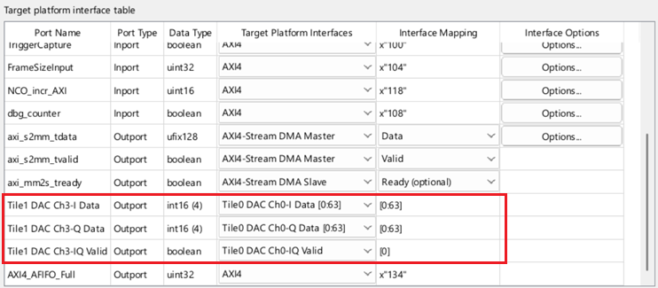
If you are using a ZCU208 board, for the Tile1 DAC Ch3-I Data port, set the target interface to Tile1 DAC Ch0-I Data. For the Tile1 DAC Ch3-Q Data port, set the target interface to Tile1 DAC Ch0-Q Data. For the Tile1 DAC Ch3-IQ Valid port, set the target interface to Tile0 DAC Ch0-IQ Valid.
In step 4.2, to generate a script that provides MATLAB connectivity to the board for interactive testing and live I/O interfacing, select Generate host interface script and clear the Generate Simulink software interface model checkbox.
To build the FPGA bitstream design, right-click Build FPGA Bitstream and click Run to Selected Task.

IQ Data Capture
To capture IQ data in this loopback test, perform a full HDL Workflow Advisor build and wait until the FPGA bitstream has been compiled. Afterward, program the board and run this capture script.
HostIO_rfsocIQDataCapture_interface.m
The capture loop triggers a register to initiate data capture logic to move IQ data into the DMA. The loop then reads the frame of IQ data and formats it to display these plots. To stop the capture, close the MATLAB plot.


Change Converter Settings: LO Mixer
You can set the LO from MATLAB by using the System object script at run time. This example provides a script to show an example of how you can use the RFSoC System to alter the mixer tone of the DAC and ADC. Open and examine this MATLAB script file: HostIO_ChangeLO_rfsocIQDataCapture.m.
In this example, this script shifts the LO tone such that the DAC experiences a shift of 10 MHz relative to the ADC LO, with a center frequency of 800 MHz.
Connect to the target board.
rfobj = soc.RFDataConverter('zu49dr','192.168.1.101');
setup(rfobj)
Specify LO Value in MHz. All tiles and channels use this LO Value.
LO_VALUE = 800;
Create a shift of 10 MHz in the DAC RF NCO.
rfobj.configureDACLocalOscillator(1,3,LO_VALUE+10);
Configure frequency of the ADC RF NCO.
rfobj.configureADCLocalOscillator(0,0,-LO_VALUE);
Disconnect the communication channel created between the soc.RFDataConverter System object and the rftool running on the SoC device.
release(rfobj)
After running this script, run the capture script again and examine the spectrum plot.
HostIO_ChangeLO_rfsocIQDataCapture
The tone, which was previously at 25 MHz, is now shifted by 10 MHz to 35 MHz.