Generate HDL Code from For Each Subsystem Blocks
R2026bThis example shows how a For Each Subsystem block implements a cascaded CORDIC (Coordinate Rotation Digital Computer) square root pipeline with a parameterized number of cores. In this example, you examine the model architecture, verify numerical accuracy against a reference function, and generate HDL code by using HDL Coder™.
A CORDIC algorithm computes mathematical functions through iterative shift-and-add micro-rotations. For a square root, each micro-rotation refines the result toward the final value.
Cascaded CORDIC Pipeline Architecture
For low-data-rate applications, you can reuse a single CORDIC core to perform the micro-rotations, which achieves a small area footprint. For high-throughput applications that require a new CORDIC result every clock cycle, you can cascade identical CORDIC cores in a pipeline. Each core performs one micro-rotation per clock cycle, and Delay blocks between stages break up the critical path.
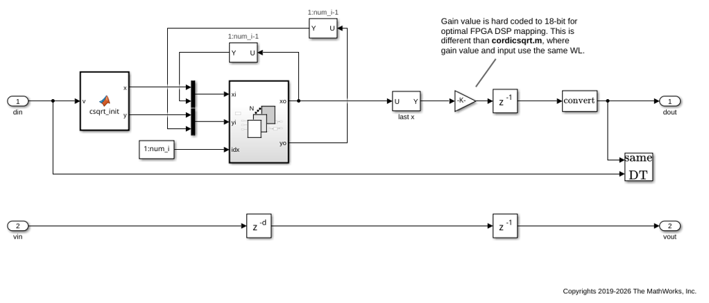
In this model, the For Each Cordic Sqrt subsystem has a mask parameter Number of iterations that controls how many CORDIC cores to cascade. Mux and Constant blocks inside the subsystem create input vectors of that length, and the For Each Subsystem block partitions each vector into single-element slices, producing one iteration per core. Changing the mask parameter scales the pipeline without manual wiring.
Open the Model
The model hdlcoder_foreach_cordic implements a 10-core cascaded CORDIC square root pipeline using a For Each Subsystem block. Open the model and the For Each Cordic Sqrt subsystem to examine the architecture.
open_system("hdlcoder_foreach_cordic")
open_system("hdlcoder_foreach_cordic/For Each Cordic Sqrt","force")
Explore the For Each Subsystem Architecture
Inside the For Each Subsystem block, the model contains:
A MATLAB Function block (
MATLAB Function1) that implements one CORDIC micro-rotation. Thecsqrt_corefunction performs a single shift-and-add iteration on the input data.Two Delay blocks (
Delay_xandDelay_y) after the core outputs. These Delay blocks act as pipeline registers that break the combinational path from input to output of each iteration.
Because the For Each Subsystem block is an atomic subsystem, the connection between the output of one iteration and the input of the next iteration creates an artificial algebraic loop. The Delay_x and Delay_y blocks eliminate this direct feedthrough. To enable Simulink® to recognize that the internal delays resolve the loop, select Minimize artificial algebraic loop occurrences in the For Each Subsystem block parameters.
Outside the For Each Subsystem block, the Selector1 and Selector2 blocks extract the outputs of cores 1 through 9 from the For Each Subsystem output vector. The Mux1 and Mux2 blocks then concatenate the initial values from the MATLAB Function2 block with these outputs to form the input vectors for the next simulation step. This feedback routing connects each core output to the next core input, forming the cascade. The last x Selector block extracts the final core output and passes it through the Gain block to produce the subsystem result.
A parallel chain of Delay blocks (Delay, Delay3, and Delay4) forms a valid signal path that tracks whether the pipeline contains valid data. You must match the valid signal path latency to the data path latency. In this model, there are 10 CORDIC cores and one output pipeline stage, for a total of 11 delays in the valid signal path.
Compare Model Output to CORDIC Square Root Reference
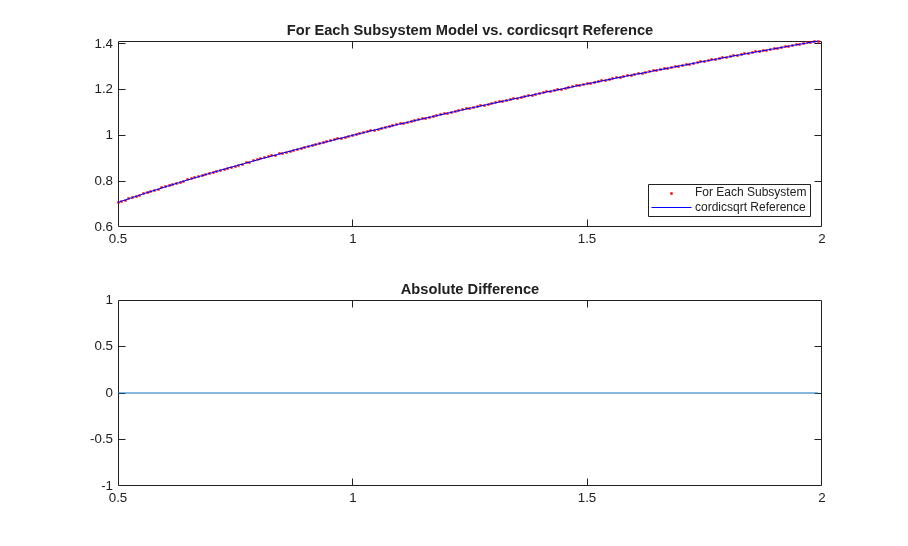
The Fixed-Point Designer™ function cordicsqrt computes the CORDIC square root using a bit-accurate reference algorithm. Use this function to verify that the Simulink model produces correct results.
The model callbacks define a 14-bit signed fixed-point input in the range [0.5, 2). For this input data type, the For Each Subsystem output matches the cordicsqrt reference exactly.
The model uses an 18-bit gain parameter sized for efficient FPGA DSP block utilization. For inputs with different word lengths, slight numerical differences from cordicsqrt can occur because of this gain quantization.
slout = sim("hdlcoder_foreach_cordic");
data_out = slout.logsout.getElement("data out").Values.Data;
valid_out = slout.logsout.getElement("valid out").Values.Data;
data_out = data_out(valid_out);

ref_cordic = double(cordicsqrt(v_fix, niter));
data_in = double(v_fix);
data_out = double(data_out');

figure;
subplot(211);
plot(data_in, data_out, "r.", data_in, ref_cordic, "b-");
legend("For Each Subsystem", "cordicsqrt Reference", Location="SouthEast");
title("For Each Subsystem Model vs. cordicsqrt Reference");
subplot(212);
absErr = abs(ref_cordic - data_out);
plot(data_in, absErr);
title("Absolute Difference");
Generate HDL Code
Generate VHDL code for the For Each Cordic Sqrt subsystem. HDL Coder replicates the CORDIC core logic for each of the 10 pipeline iterations.
evalc('makehdl("hdlcoder_foreach_cordic/For Each Cordic Sqrt")');
Limitations
When you use delays inside a For Each Subsystem block for pipelining:
The internal Delay blocks can cause compatibility issues with Clock Rate Pipelining (CRP) in designs that use oversampling. If your design requires CRP with oversampling, place pipeline registers outside the subsystem or use an alternative architecture.
See Also
For Each Subsystem | For Iterator Subsystem | cordicsqrt

