Generate HDL Code for Blocks Inside For Each Subsystem
This example shows how to use blocks inside a For Each Subsystem in your Simulink® model, and then generate HDL code.
Why Use a For Each Subsystem?
To repeatedly perform the same algorithm on individual elements or subarrays of the input signals, use the For Each Subsystem block. The set of blocks within the Subsystem replicate the algorithm that is applied to individual elements or equally divided subarrays of the input signals. Using the For Each Subsystem block, you do not have to create and connect replicas of a Subsystem block to model the same algorithm. The For Each Subsystem:
Supports vector or 2-D matrix processing, which reduces the simulation time of your model. You can process individual elements or subarrays of an input signal simultaneously.
Improves code readability by using a for-generate loop in the generated HDL code. The for-generate loop reduces the number of lines of code, which can otherwise result in hundreds of lines of code for large vector signals.
Supports HDL code generation for all data types, Simulink blocks, and predefined and user-defined system objects.
Supports optimizations on and inside the block, such as resource sharing and pipelining. The parallel processing capability of the For Each Subsystem block combined with the optimizations that you specify produces high performance on the target FPGA device.
Modeling With the For Each Subsystem
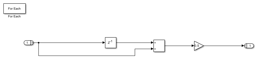
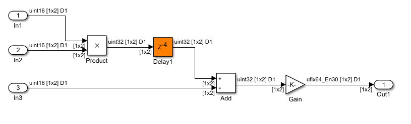
Open the foreach_subsystem_example1 model. You see this simple algorithm modeled inside a For Each Subsystem block.

When you simulate the model, you see that the input signals In1 and In3 are partitioned into subarrays. To see this partitioning, double-click the For Each block. The block parameters Partition Dimension and Partition Width specify the dimension through which the input signal is partitioned and the width of each partition slice respectively. Based on the input signal sizes and the partitioning that you specify, the For Each Subsystem determines the number of iterations that it requires to compute the algorithm.
In this example, the input signals In1 and In3 of size 8 are partitioned into four subarrays, each of size 2. The input signal In2 of size 2 is not partitioned. To compute the algorithm, the For Each Subsystem requires four iterations, with each iteration repeating the algorithm on each of the four subarrays of In1 and In3.
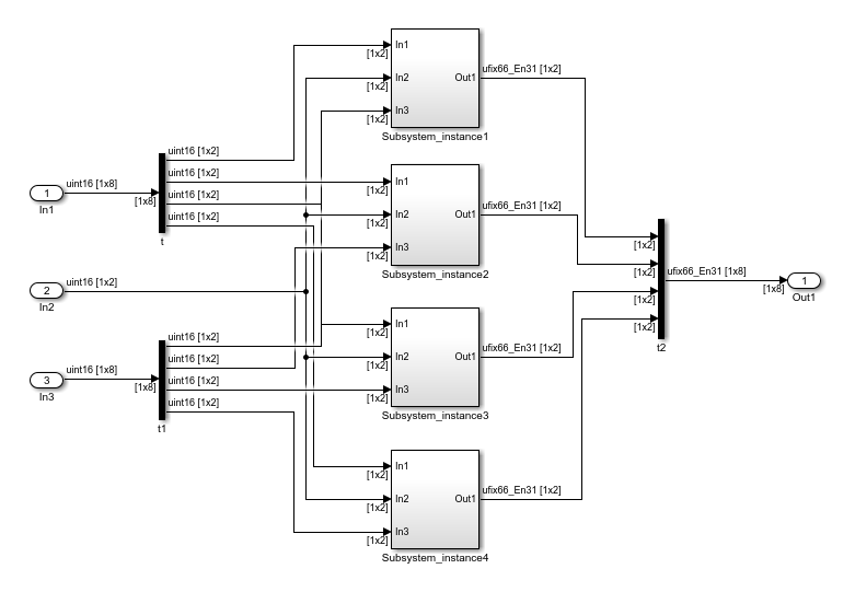
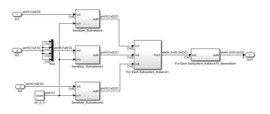
The For Each Subsystem simplifies modeling of vectorized algorithms. This figure shows how you can model the same algorithm by creating multiple subsystem instances. This model can become graphically complex and difficult to maintain.
Using Matrix Input Signals
The For Each Subsystem supports 2-D matrix input for HDL code generation. For example, the foreach_subsystem_example2 model shows a simple multi-channel filter operation. HDL code generation is not supported for matrices at the input and output ports of the HDL DUT, so the model separates the channels at the DUT subsystem boundary.
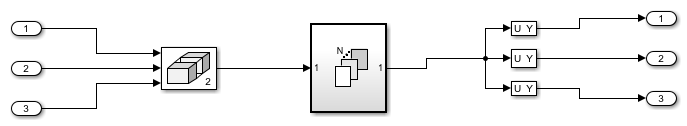
The For Each subsystem averages the samples on each channel. The generated HDL code will contain three copies of the logic inside the For Each Subsystem, and each operates on a 4x1 vector.
Using Complex Data Signals
The block does not support complex data types as inputs for HDL code generation. To input a complex signal, you can convert this signal to an array of signals, and then input to the block.
To perform the same algorithm on both real and imaginary parts of the signal:
Separate the signal into real and imaginary parts by using a Complex to Real-Imag block.
Create a vector signal that consists of the real and imaginary parts by using a Mux block.
You can then input this vector to the For Each Subsystem block and replicate the same computation on both the real and imaginary parts. At the output of the For Each Subsystem, you can convert the vector output back to a complex signal. Use a Demux block to separate the real and imaginary scalar parts, and then input the scalars to the Real-Imag to Complex block.
Generate HDL Code
To generate HDL code in the foreach_subsystem_example1 model, right-click the Subsystem_Foreach block. To add HDL Coder app options to the context menu, point to Select Apps, and click HDL Coder. Then, in the HDL Coder app section, select Generate HDL for Subsystem.
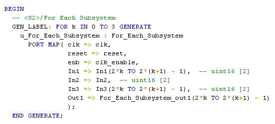
To see the generated HDL code for the Subsystem_Foreach block, in the MATLAB® Command Window, click the Subsystem_Foreach.vhd file. In the VHDL® code snippet, you see this for-generate loop in the HDL code. This loop creates four subsystem instances, with each instance performing the algorithm on size 2 subarrays of inputs In1 and In3.
You can specify optimizations that change the contents of the subsystems that the For Each Subsystem instantiates. In such cases, the code generator does not use for-generate loops in the HDL code. The HDL code does not contain for-generate loops if you have:
Bus or complex input signals.
Resource sharing and streaming optimizations on the subsystem.
Vector inputs that get partitioned into nonscalar signals in the Verilog® code. To obtain for-generate loops in the Verilog code, partition the vector signal to scalars.
Optimize the For Each Subsystem Algorithm
To optimize the algorithm contained within the For Each Subsystem, you can enable optimizations such as resource sharing and streaming on the DUT that contains the For Each Subsystem. For example, by using the resource sharing optimization, you can share multiple Subsystem instances that are created by the For Each Subsystem. This optimization reuses the algorithm modeled by the Subsystem across multiple instances and reduces the area usage on the target device.
Note: When you enable optimizations on the For Each Subsystem, the generated HDL code does not contain for-generate loops.
This example shows how to apply the resource sharing optimization to a For Each Subsystem. To share resources, select the Subsystem block that contains the For Each Subsystem and specify the Sharing Factor. In this example, right-click the Subsystem_Foreach block and, in the HDL Coder section of the Simulink context menu, select HDL Block Properties. Set the Sharing Factor to 4, because the For Each Subsystem generates four subsystem instances. Then, generate HDL code for the Subsystem_Foreach block.
To see the effect of the resource sharing optimization, at the command-line, enter gm_foreach_subsystem_example1 to open the generated model. In the generated model, you see that the optimization shared the four subsystem instances generated by the For Each Subsystem into one Subsystem For Each Subsystem_Instance1.
If you double-click the For Each Subsystem_Instance1 block, you see the algorithm computed for the size 2 subarrays of inputs In1 and In3.
To learn more about the resource sharing optimization, see Resource Sharing.