Debug and Control Generated HDL IP Core by Using JTAG AXI Manager
This example shows how to specify automatic insertion of the HDL Verifier™ AXI Manager IP into a reference design. This example also explains how to use MATLAB® or Simulink® to configure the HDL Coder™ generated FPGA IP core.
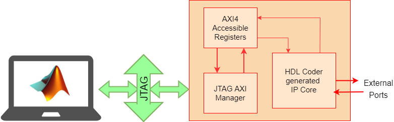
To access onboard memory locations and quickly probe or control the FPGA logic from
MATLAB or Simulink, use the JTAG AXI Manager IP. The aximanager
System object™ you create in MATLAB connects to the AXI Manager IP over a physical JTAG cable and allows you
to run read and write commands to subordinate memory locations from the MATLAB command line. In Simulink, the AXI Manager
Read (HDL Verifier) and AXI Manager
Write (HDL Verifier) blocks drive AXI Manager IP to perform read and write operations on
output and input ports of the HDL Coder generated device under test (DUT) over the JTAG
interface.
This example uses ZedBoard™ to implement the FPGA design.
Debug and Control Generated HDL IP Core by using JTAG AXI Manager
Requirements
HDL Verifier™ Support Packages for Xilinx FPGA Boards
HDL Coder™ Support Package for AMD® FPGA and SoC Devices
Xilinx® Vivado™ Design Suite, with the supported version listed in HDL Language Support and Supported Third-Party Tools and Hardware
ZedBoard
Generate Reference Design with AXI Manager IP
Set up the Xilinx Vivado tool path. Use your own Xilinx Vivado installation path when executing the hdlsetuptoolpath function.
hdlsetuptoolpath("ToolName","Xilinx Vivado","ToolPath", ...
                 vivadopath);
Enable Insertion of JTAG AXI Manager
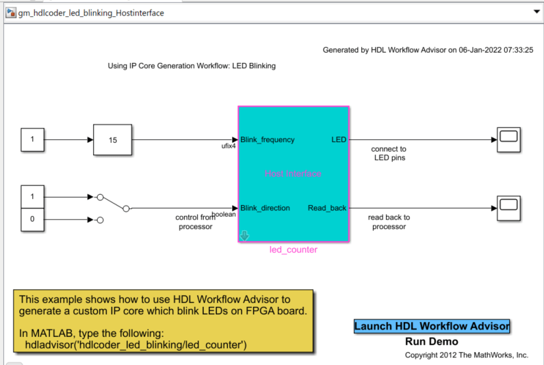
1. Open the hdlcoder_led_blinking model by running this command at the MATLAB command prompt.
open_system("hdlcoder_led_blinking")
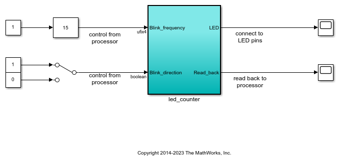
This example implements the led_counter subsystem on the hardware. This subsystem models a counter that causes LEDs to blink on the hardware. Two input ports, Blink_frequency and Blink_direction, are control ports that determine the LED blink frequency and direction, respectively. The output port LED connects to the LEDs on the hardware. You can use the output port Read_back to read data back to MATLAB.
2. Open the HDL Workflow Advisor. Select the hdlcoder_led_blinking/led_counter subsystem. On the Apps tab, click HDL Coder. On the HDL Code tab, in the Assistance section, click Workflow Advisor.
3. In the Set Target > Set Target Device and Synthesis Tool task, set Target workflow to IP Core Generation.
4. Set Target platform to ZedBoard. If you do not see this option, select Get more to open the Support Package Installer. In the Support Package Installer, select Xilinx Zynq Platform and follow the instructions provided by the Support Package Installer to complete the installation.
5. Click Run This Task to run the Set Target Device and Synthesis Tool task.
6. In the Set Target > Set Target Reference Design task, choose Default system and set the Insert AXI Manager (HDL Verifier required) reference design parameter to JTAG.
7. Click Run This Task to run the Set Target Reference Design task.
Generate HDL IP Core and Create Project with AXI Manager IP
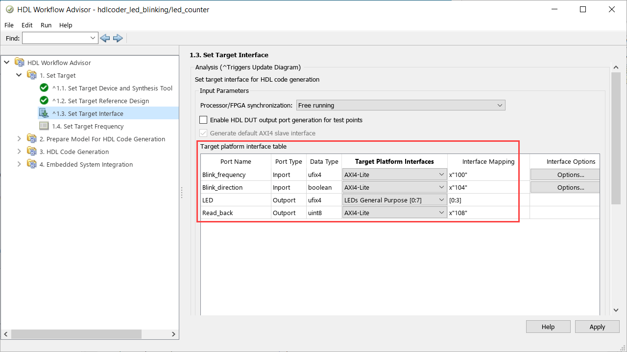
Map each port in your DUT to one of the IP core target interfaces. This example maps the Blink_frequency and Blink_direction input ports to the AXI4-Lite interface, so the HDL Coder generates registers that can be accessed through the AXI interface for these ports. This example maps the LED output port to an external interface, LEDs General Purpose [0:7], which connects to the LED hardware on the ZedBoard.
1. In the Set Target > Set Target Interface task, choose AXI4-Lite for Blink_frequency, Blink_direction, and Read_back.
2. Choose LEDs General Purpose [0:7] for LED.
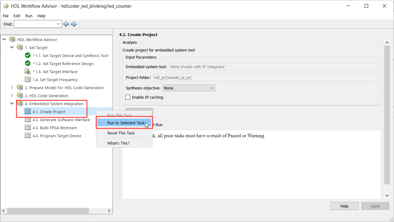
3. Create the reference design project, which includes JTAG AXI Manager.
To create the project, right-click the Create Project task and select Run to Selected Task.
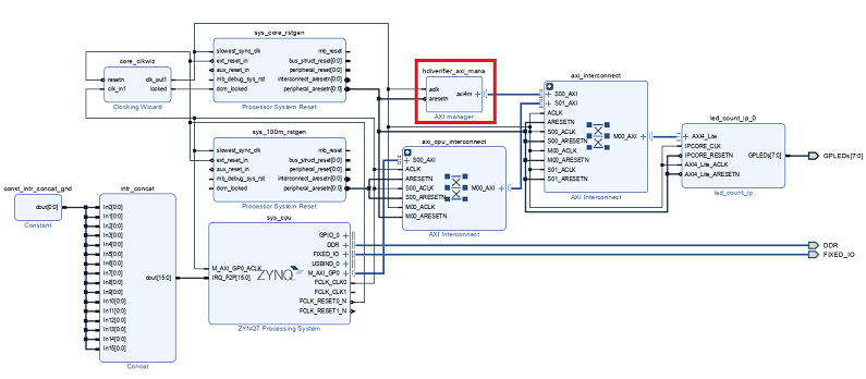
In the Vivado project, you can see the JTAG AXI Manager IP inserted in the reference design. If the target frequency in the Set Target Frequency task is less than or equal to 100 MHz, the software uses this reference design and the JTAG AXI Manager IP is driven by the DUT clock.
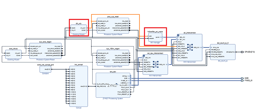
If the target frequency in the Set Target Frequency task is greater than 100 MHz, the software uses this reference design and the JTAG AXI Manager IP is driven by the 50 MHz fixed clock generated by clk_wiz_IO to avoid any timing failures.
Generate Host Interface Model
Generate the host interface model by replacing the DUT with the AXI Manager Read (HDL Verifier) and AXI Manager Write (HDL Verifier) blocks in the Simulink model. Follow these steps to generate the host interface model.
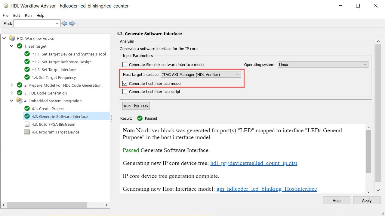
1. In the Embedded System Integration > Generate Software Interface task, set Host target interface to JTAG AXI Manager (HDL Verifier).
2. Select Generate host interface model.
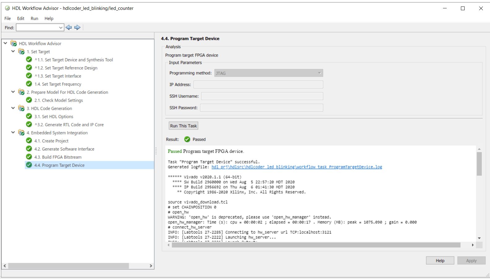
3. Click Run This Task.
The following screen shot shows the gm_hdlcoder_led_blinking_Hostinterface.slx host interface model. You can use the host interface model as a Simulink test bench to tune DUT registers.
Run the remaining steps in the workflow to generate a bitstream and program the target device.
Control HDL Coder IP Core Using JTAG AXI Manager
Simulink Model to Control HDL Coder IP Core
1. Open the gm_hdlcoder_led_blinking_Hostinterface model.
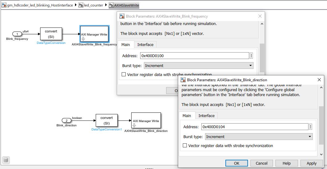
2. Go to gm_hdlcoder_led_blinking_Hostinterface > led_counter > AXI4SlaveWrite subsystem. Configure the AXI Manager Write (HDL Verifier) block.
This figure shows the default configuration of the AXI Manager Write block for the current HDL Workflow Advisor configuration.
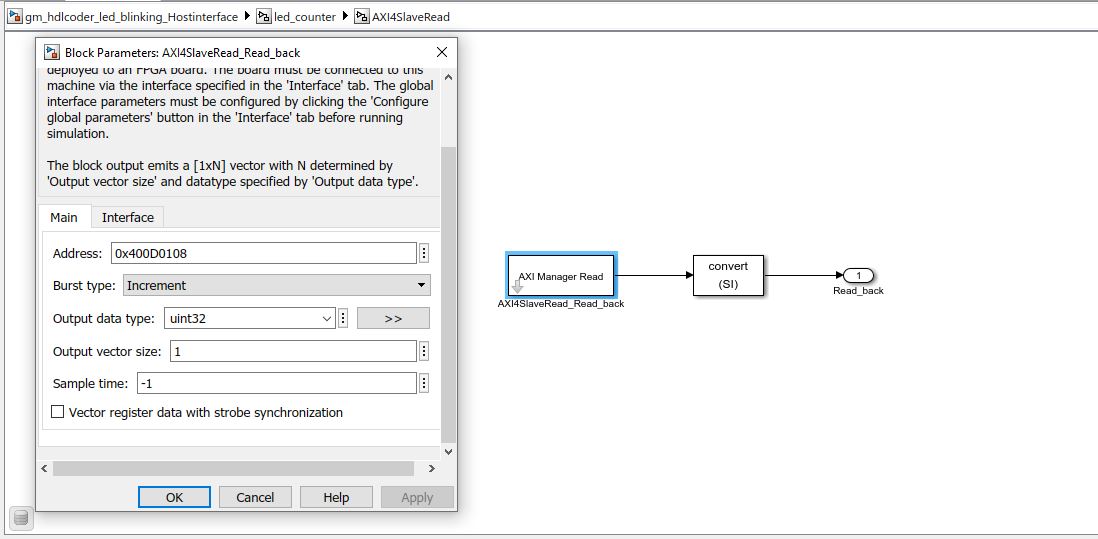
3. Go to the gm_hdlcoder_led_blinking_Hostinterface > led_counter > AXI4SlaveRead subsystem. Configure the AXI Manager Read (HDL Verifier) block.
This figure shows default configuration of the AXI Manager Read block for the current HDL Workflow Advisor configuration.
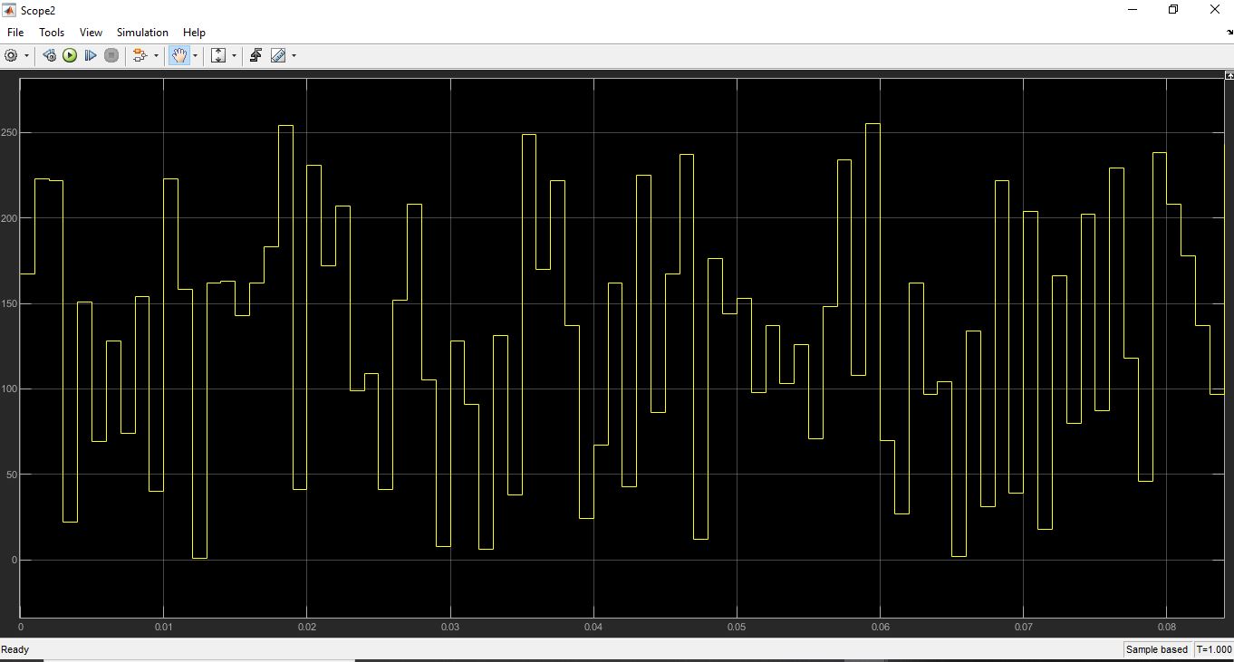
Run the gm_hdlcoder_led_blinking_Hostinterface model to perform read and write operations from Simulink.
The figure shows Read_back register (LED output) samples over time.
MATLAB Command Line Interface
You can also control the DUT from the MATLAB command line by creating an object for AXI Manager IP.
1. Create the AXI manager object.
h = aximanager("Xilinx")
2. Change the LED blinking frequency.
h.writememory("400D0100",0)
Observe that the LED blinking frequency is low. Change the frequency from 0 to 15 to increase the LED blinking frequency.
h.writememory("400D0100",15)
3. Read the current counter value.
h.readmemory("400D0108",1)
4. Delete the object when done to free up the JTAG resource. If you do not delete the object, any other JTAG operation fails.
delete(h)
JTAG AXI Manager in Custom Reference Designs
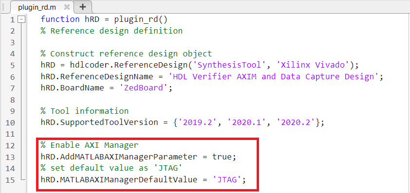
The Insert AXI Manager (HDL Verifier required) reference design parameter is by default added to your custom reference design. The default value for the parameter is off. In custom reference design, you can control this parameter by using the following properties.
AddMATLABAXIManagerParameter - Control visibility of the Insert AXI Manager parameter.
MATLABAXIManagerDefaultValue - Specify whether to insert the AXI manager IP.
You can set the Insert AXI Manager (HDL Verifier required) parameter to display in Set Target Reference Design task and assign the default value as JTAG by adding the properties in the plugin_rd.m file of the custom reference design workflow shown in this figure.