Pressure-Reducing 3-Way Valve (IL)
Combined pressure-relief and pressure-reducing valve in an isothermal liquid system

Libraries:
Simscape /
Fluids /
Isothermal Liquid /
Valves & Orifices /
Pressure Control Valves
Description
The Pressure-Reducing 3-Way Valve (IL) is a combination of a pressure-relief and pressure-reducing valve. It maintains pressure at the valve outlet, port A, by restricting the inflow area at port P and venting the flow at port T.
Valve Functionality
The block controls the valve operation by comparing the pressure difference between port A and port T to a set of pressure threshold ranges. When the pressure difference between A and T, Pcontrol, exceeds Pset,reducing, port P begins to close. When Pcontrol is between Pset,reducing+Preg and Pset,reducing+ Preg+Ptransition, the block is in a transition range and both valves at ports P and T are closed. When Pcontrol exceeds the pressure transition range, Pset,relief, where , port T begins to open.
To simulate pressure relief or pressure reduction with respect to another system element, see Pressure Compensator Valve (IL). To simulate pressure reduction between the valve outlet and atmosphere, see the Pressure-Reducing Valve (IL). To simulate pressure relief with respect to a valve or between the valve outlet and atmospheric pressure, see Pressure Relief Valve (IL).
Pressure Control
When Pcontrol, PA – PT, exceeds the threshold pressure, Pset,reducing, the valve at port P begins to close. When the pressure exceeds the transition range, or when Pcontrol > Pset,relief, the valve at port T begins to open. Both valve closing and opening are parameterized in two ways:
When Set pressure control is
Controlled, the block uses the pressure signal at port Ps to control the valve. In this setting, Preg is the value of the Pressure regulation range parameter, and Ptransition is the value of the Pressure transition range parameter. The pressure-reducing valve begins to close when Pcontrol is greater than Pset,reducing, which is the value of the signal at port Ps. The relief valve response is triggered, meaning port T starts to open, when Pcontrol is greater than Pset,relief and below Pmax,relief. Pmax,relief is the sum of the value of the Pressure regulation range parameter and Pset,relief.When Set Pressure control is
Constant, the valve closing at port P is continuously regulated by either a linear or tabular parameterization. Similarly, relief valve opening at port T is parameterized linearly or by table lookup. An example of linear parameterization of the reduction valve (solid line) and relief valve (dotted line) is shown below.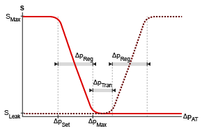
If you set Opening parameterization to
Linear, Pset,reducing is the value of the Set pressure differential for reducing valve parameter, Preg is the value of the Pressure regulation range parameter, and Ptransition is the value of the Pressure transition range parameter. Pmax,relief is the sum of the value of the Pressure regulation range parameter and Pset,relief.If you set Opening parameterization to
Tabulated, Pset,reducing and Pmax,reducing are the first and last parameters of the Pressure differential vector for reducing valve, respectively, and Pset,relief and Pmax,relief are the first and last parameters of the Pressure differential vector for relief valve, respectively. An example of tabular parameterization of both the reducing and relieving valves are shown below.
Mass Flow Rate Equation
Momentum is conserved through the valve:
The mass flow rate through the valves is calculated as:
where:
Cd is the value of the Discharge coefficient parameter.
A is the instantaneous valve open area between ports A and P or A and T, as indicated by the subscript.
Aport is the value of the Cross-sectional area at ports A, P & T parameter.
is the average fluid density.
Δp is the valve pressure difference, pA – pB.
The critical pressure difference, Δpcrit, is the pressure differential associated with the Critical Reynolds number, Recrit, the flow regime transition point between laminar and turbulent flow, which corresponds to either the pressure-reducing or pressure relief component of the valve,
where A is either APA or AAT, corresponding to the reducing or relief component of the valve, respectively.
Pressure loss describes the reduction of pressure in the valve due to a decrease in area. PRloss is
Pressure recovery describes the positive pressure change in the valve due to an increase in area. If you do not want to capture this increase in pressure, clear the Pressure recovery checkbox. In this case, PRloss is 1.
When Set Pressure control is Constant, the
block calculates the opening area A by using the opening
parameterization of the reducing valve (P to
A) or relief valve (A to
T) and the valve opening dynamics.
Opening and Closing Parameterization
When you set Opening parameterization to
Linear, the valve area for the reducing valve is
and for the relief valve is
The normalized pressure, , is
where the set and maximum pressures are the respective reducing or relief valve settings.
When the valve is in a near-open or near-closed position in the linear parameterization, you can maintain numerical robustness in your simulation by adjusting the Smoothing factor parameter. If the Smoothing factor parameter is nonzero, the block smoothly saturates the control pressure between pset and pmax. For more information, see Numerical Smoothing.
When you set Opening parameterization to
Tabulated,
Aleak,PA and
Amax,PA are the first and last
elements of the Opening area vector reducing valve parameter,
respectively, and Aleak,AT and
Amax,AT are the first and last
elements of the Opening area vector for relief valve parameter,
respectively. The block calculates the opening area as
For the reducing valve, the block calculates the opening area by using the table lookup method, where:
pcontrol is the control pressure, which is the pressure differential between ports A and T.
pcontrol,TLU,ref = pTLU + poffset.
pTLU is the Pressure differential vector for reducing valve parameter
poffset is an internal pressure offset that causes the valve to start closing when pcontrol,TLU,ref = pset,reducing.
ATLU is the Opening area vector reducing valve parameter.
For the relief valve, the block calculates the opening area by using the table lookup method, where:
pcontrol is the pressure differential between ports A and T.
pcontrol,TLU,ref = pTLU + poffset.
pTLU is the Pressure differential vector for relief valve parameter.
poffset is an internal pressure offset that causes the valve to start opening when pcontrol,TLU,ref = pset,releif.
ATLU is the Opening area vector for relief valve parameter.
Opening Dynamics
When you select Opening dynamics, the block applies a first-order filter to the valve area based on the Opening time constant parameter, τ. The valve area, Avalve, becomes the dynamic area, Adyn,
When you select Opening dynamics, the valve does not respond to changes instantaneously. This figure shows an example valve area in response to a step in the valve input pressure with and without opening dynamics:
When you clear Opening dynamics, the valve area mirrors the step change in the pressure at the input.
When you select Opening dynamics and set Opening time constant to
0.1 s, the valve area asymptotically approaches its limit.
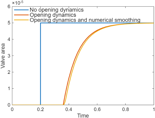
Specifying a nonzero value for the Smoothing factor parameter provides additional numerical stability when the valve area is changing and in the near-closed or near-open position. For more information, see Numerical Smoothing.
Faults
To model a fault, in the Faults section, click the Add fault hyperlink next to the fault that you want to model. Use the fault parameters to specify the fault properties. For more information about fault modeling, see Introduction to Simscape Faults.
The Valve areas when faulted parameter has three fault options:
Reducing valve closed and relief valve open— The reducing valve freezes at its smallest value and the relief valve freezes at its largest value, depending on the Opening parameterization:When Opening parameterization is set to
Linear, the reducing valve area freezes at the value of the Leakage area parameter and the relief valve area freezes at the value of the Maximum opening area parameter.When Opening parameterization is set to
Tabulated, the reducing valve area freezes at the value of the first element of the Opening area vector parameter and the relief valve area freezes at the value of the last element of the Opening area vector parameter.
Reducing valve open and relief valve closed— The reducing valve freezes at its largest value and the relief valve freezes at its smallest value, depending on the Opening parameterization:When Opening parameterization is set to
Linear, the reducing valve area freezes at the value of the Maximum opening area parameter and the relief valve freezes at the value of the Leakage area parameter.When Orifice parameterization is set to
Tabulated, the reducing valve area freezes at the value of the last element of the Opening area vector parameter and the relief valve area freezes at the value of the first element of the Opening area vector parameter.
Maintain last value— The reducing and relief valve areas freeze at the open area when the trigger occurred.
Due to numerical smoothing at the extremes of the valve area, the minimum area the block uses is larger than the value of the Leakage area parameter, and the maximum is smaller than the value of the Maximum orifice area parameter, in proportion to the Smoothing factor value.
After the fault triggers, the valves remain at the faulted area for the rest of the simulation.
Assumptions and Limitations
Friction between the valve and fluid, the hydraulic force of the fluid on the valve components, and the effect of fluid inertia are neglected.