Tank (G-IL)
Libraries:
Simscape /
Fluids /
Isothermal Liquid /
Tanks & Accumulators
Description
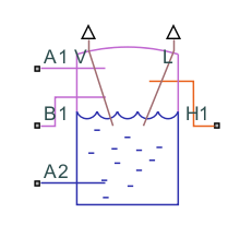
The Tank (G-IL) block models the accumulation of mass and energy in a chamber with separate gas and isothermal liquid volumes. The total fluid volume is fixed, but the individual gas and isothermal liquid volumes can to vary. Two gas ports allow for gas flow and a variable number of isothermal liquid ports, ranging from one to six, allow for isothermal liquid flow. The isothermal liquid ports can be at different elevations.

The tank is pressurized, but the pressurization is not fixed. It changes during simulation corresponding to the pressure in the gas volume. The pressure rises when the pressure of the gas volume rises and falls when the pressure of the gas volume falls. The block assumes that the isothermal liquid volume is at equilibrium with the gas volume and its pressure is the same as that of the gas. The two fluid volumes go not exchange energy with each other, but energy exchanges with other components can occur through the gas ports.
Isothermal Liquid Ports
You can specify the number of isothermal liquid ports using the Number of inlets parameter:
| Number of inlets | Exposed isothermal liquid ports |
|---|---|
1 | Port A2 |
2 | Ports A2 and B2 |
3 | Ports A2, B2, and C2 |
4 | Ports A2, B2, C2, and D2 |
5 | Ports A2, B2, C2, D2, and E2 |
6 | Ports A2, B2, C2, D2, E2, and F2 |
Fluid Volumes
The total volume of the tank is the sum of the gas and isothermal liquid volumes that it contains,
where V is the volume and T, L, and G stand for total, liquid, and gas. Because the total volume is fixed, the time rate of change of the gas volume must be the reverse of the time rate of change for the isothermal liquid volume,
The block calculates the time rate of change of the isothermal liquid volume by differentiating the expression
where M is mass and ρ is density. The differentiation gives the mass flow rate into the isothermal liquid volume,
The rate of change of the isothermal liquid volume and, by extension, of the gas volume is
where p is the pressure.
Mass Balance
The rate of mass accumulation in each fluid volume is equal to the net mass flow rate into that fluid volume. In the isothermal liquid volume
where ML is the rate of mass accumulation in the isothermal liquid volume and are the individual mass flow rates into that volume through the isothermal liquid ports A2, B2, C2, D2, E2, or F2.
In the gas volume
MG is the rate of mass accumulation in the gas volume and are the individual mass flow rates into that volume through the gas ports A1 and B1. The rate of mass accumulation for the gas volume contains contributions from pressure, temperature, and volume change,
where T is the temperature and the pressure and temperature derivatives depend on the type of gas specified in the Gas Properties (G) block. The equations section of the Translational Mechanical Converter (G) page defines the derivatives. The mass balance equation for the gas volume is
Energy Balance
The rate of energy accumulation in the gas volume is
where:
U is the total energy of the fluid volume.
h is the fluid enthalpy.
Q is the heat flow rate through the thermal port.
ϕi are the energy flow rates through the fluid inlets.
The pressure and temperature derivatives depend on the type of gas specified in the Gas Properties (G) block. See the equations section of the Translational Mechanical Converter (G) page for the definitions.
Momentum Balance
The block ignores flow resistance due to friction or other causes in both fluid volumes. The block also ignores the effect of elevation on inlet pressure, but only on the gas side. The gas inlet pressures are equal to each other and to the internal pressure of the gas volume:
The isothermal liquid inlet pressures are each a function of inlet depth. The internal pressure of the isothermal liquid volume is equal to the gas volume, pL = pG. The block includes dynamic pressures, pi,dyn, at the inlets by using the equation
where y is the elevation of the isothermal liquid surface, yi is the elevation of the isothermal liquid inlet, and g is the gravitational constant. The term y - yi gives the depth of the isothermal liquid inlet with respect to the gas-isothermal liquid boundary. The dynamic pressure at each isothermal liquid inlet depends on the direction of flow at that inlet
where vi is the flow velocity.
Variables
To set the priority and initial target values for the block variables prior to simulation, use the Initial Targets section in the block dialog box or Property Inspector. For more information, see Set Priority and Initial Target for Block Variables and Initial Conditions for Blocks with Finite Gas Volume.
Nominal values provide a way to specify the expected magnitude of a variable in a model. Using system scaling based on nominal values increases the simulation robustness. Nominal values can come from different sources, one of which is the Nominal Values section in the block dialog box or Property Inspector. For more information, see Modify Nominal Values for a Block Variable.
Assumptions and Limitations
Fluid momentum is lost at the tank inlet due to the sudden expansion into the tank volume.
Examples

Electric Vehicle Thermal Management
Model the thermal management system of a battery electric vehicle.
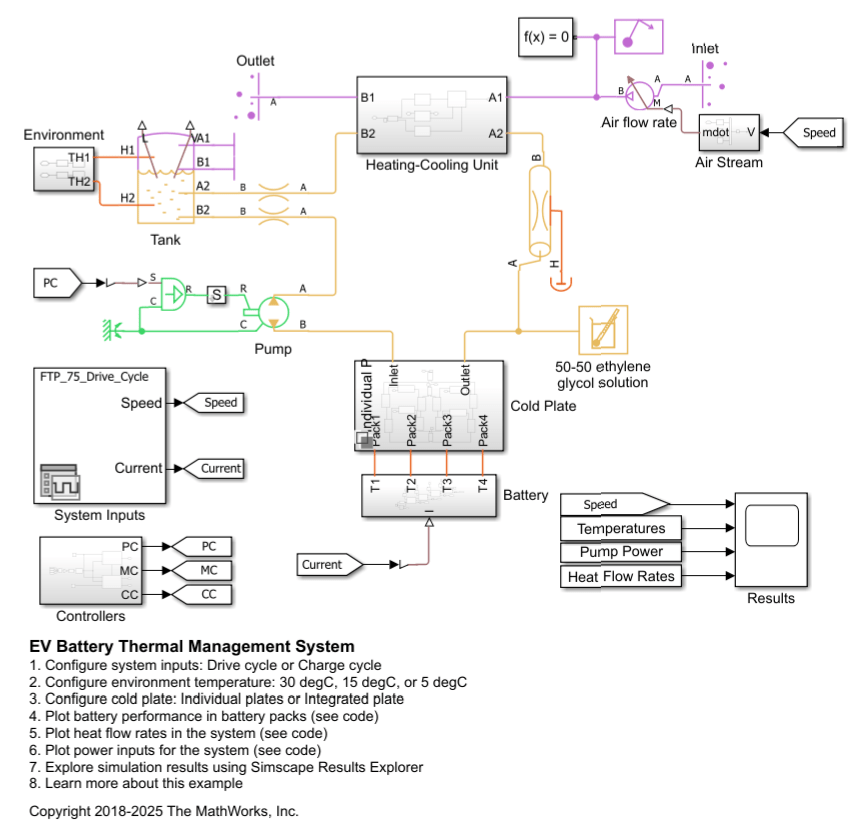
EV Battery Thermal Management System
An Electric Vehicle (EV) battery heating-cooling system. Maintaining the battery temperature within an optimal range is important for efficient charging and discharging. The model simulates either the FTP-75 drive cycle or a fast charge cycle at different environment temperatures. A thermal liquid coolant circuit conveys heat between the battery and the heating-cooling unit. For more information on designing EV battery cooling systems, see EV Battery Cooling System Design.
Ports
Output
Conserving
Parameters
Extended Capabilities
Version History
Introduced in R2023b