Hydrostatic Transmission with Shuttle Valve
This example shows a hydrostatic transmission with a control unit that uses a shuttle valve. In the control unit, the valve actuator controls the 4-way directional valve that connects the motor to the pressure line. When one or both of the two 3-way directional valves (Shuttle A Valve and Shuttle A1 Valve) open, the shuttle valve applies force to the valve actuator so that the 4-way valve connects the motor to the pressure line. A fixed orifice is connected to the P ports of the 3-way directional valves to decrease flow consumption of the control unit. Another fixed orifice models a small leak from the valve actuator, which prevents the control unit from being isolated from the main flow.
Model

Valve Block Subsystem

Simulation Results from Scopes

Simulation Results from Simscape Logging
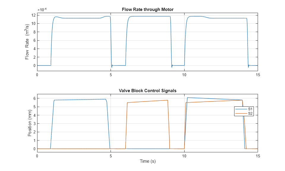
The plots below show the flow rate through the motor and the control signals to the control unit. The control unit connects the motor to the high pressure side of the pump at 1, 6, and 10 seconds by opening the Shuttle A1 Valve, the Shuttle A Valve, and both, respectively.
