Modeling Directional Valves in Simscape Fluids
Directional valves control the path a fluid takes in a system. In Simscape™ Fluids™, you can use directional valves to manage the path of the fluids in a model and parameterize the valves to specify the flow area.
Directional valves connect different flow paths based on the displacement of a spool. In Simscape Fluids, you can use the two-way, three-way, four-way, and N-way valve blocks to model directional valves. The block name describes the number of connecting ports and the number of positions the valve can assume. For example, the 4-Way 3-Position Directional Valve (TL) block models a valve with four ports and three possible spool positions: positive, negative, and neutral.
Representing Directional Valve Diagrams with Simscape Fluids Blocks
The initial open flow path, the flow paths that open or close with spool displacement, and the orifice opening offset define how the directional valve functions. Directional valve schematics show the orifice connections for each spool position. Use the directional valve diagram to parameterize the open connection parameters in your block for each spool potion.
This figure shows a four-way, three-position directional valve that has all ports closed in the neutral position. The valve, when connected to a double-acting actuator, looks like this:
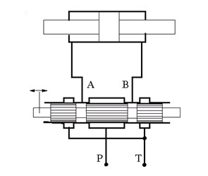
When the spool displaces in the positive direction, to the right in the valve diagram, flow paths P-A and B-T open. When the control member displaces in the negative direction, which is in the left direction in the valve diagram, flow paths P-B and A-T open. This configuration for positive and negative displacement is represented in a valve diagram as:

where the box on the left represents the positive spool displacement connections, and the box on the right represents the negative spool displacement connections.
The directional valve block port names correspond with common connections and labels in valve diagrams:
P — Pump or pressure port
T — Tank or return port
A, B — Load ports
X, Y — Pilot ports
In a block, this diagram corresponds to these block parameter settings:
Positive spool position open connections is
P-A, B-TNeutral spool position open connections is
All closedNegative spool position open connections is
P-B, A-T
Additional flow configurations may open as the spool transitions between positive and negative positions. For example, you can set a 4-Way 2-Position Directional Valve block to this valve configuration

by using these parameter settings:
Positive spool position open connections is
P-A, P-BNegative spool position open connections is
P-A, B-T
With these settings the P-A, P-B, and B-T flow paths are open when the spool transitions between the positive and negative positions. You can determine which flow paths are open by visualizing the opening characteristics of each orifice in the valve. In the block dialog box, click the Plot button next to Valve characteristics. The figure shows that as the spool leaves the negative or positive position, all three flow paths open.

Parameterizing Directional Valve Blocks
In the isothermal liquid, thermal liquid, and two-phase fluid directional valve blocks, the Spool position at maximum orifice area parameter indicates the absolute spool position at which that orifice is fully open. For orifices specified in the Positive spool position open connections parameter, the value of the Spool position at maximum orifice area parameter is typically positive. For orifices specified in the Negative spool position open connections parameter, the value of the Spool position at maximum orifice area parameter is typically negative. Any orifice not specified in the Neutral spool position open connections parameter is typically closed when the spool position is 0.
The Spool travel between closed and open orifice parameter is
the stroke that opens the orifice. If the Area characteristics
parameter is Different for each flow path, you can define the
spool travel between the closed and open orifice differently for each flow path.
To check that the pool positions for each orifice opening and closing position are a
consistent configuration, the Consistency check for neutral spool position
open connections parameter can notify you if parameterization values are
inconsistent when the spool is in the neutral position. If you set the parameter to
Warning or Error and the
parameterization values are inconsistent, the block generates a warning or error,
respectively, when you plot or refresh the plot of the valve configuration.
In the directional valve blocks in the gas domain, you do not directly specify the spool positions. The orifice opening areas depend on the method specified by the Valve parameterization parameter. The Valve Opening Fraction Offsets parameters, such as the Between ports P and A parameter, identify the orifice opening fractions. These parameters correspond to the spool position at the orifice minimum opening.
For more information on parameterizing the M-Way N-Position Valve (IL) block, see Parameterize an M-Way N-Position Valve.
Pre-Parameterized Part Data
For some isothermal and thermal liquid directional valve blocks, you can select a pre-parameterization based on manufacturer data sheets. You can control the parameterization from the set in the description section of the block dialog box. To learn more, see Simscape Fluids Part Collection.
Parameterization with a Data Sheet
If a block does not have pre-parameterization data, or you want to input data from a data sheet that is not supported, you can manually enter the information from a data sheet. Manufacturer data sheets typically provide flow rate–pressure differential curves for the different flow paths of a directional valve. You can parameterize a directional valve block with data from the manufacturer by setting the Orifice parameterization parameter to a tabulated option and using the Graph Data Extractor app to import graph data from part data sheets.
Visualizing a Valve Configuration
In the isothermal liquid, thermal liquid, and two-phase fluid 4-Way 3-Position Directional Valve and 4-Way 2-Position Directional Valve blocks, you can visualize the orifice area for each flow path as a function of spool position. For example, this image shows a four-way, three-position valve configured with these parameter settings:
Positive spool position open connections is
P-A, B-TNeutral spool position open connections is
A-T, B-TNegative spool position open connections is
P-B, A-TArea characteristics is
Different for each
                        flow path
Orifice parameterization is
Tabulated data
                        - Volumetric flow rate vs. spool travel and pressure
                     drop
Additionally, these parameter values are different from the block defaults:
Spool position at maximum A-T orifice area is
-0.004mSpool position at maximum B-T orifice area is
0.006mB-T orifice spool travel vector, ds is
[0,
                        .00125, .0025, .00375, .0065]
m.

The visualization shows that orifices A-T and B-T are open when the spool position is at 0 m. Orifice B-T is fully closed when the spool displaces to -0.0005 m, is fully open at 0.006 m, and has an opening length of 0.0065 m. Orifice A-T is fully closed at 0.001 m, is fully open at -0.004 m, and has an opening length of 0.005 m. You can also identify these values by subtracting the values of the first and last elements of the Orifice spool travel vector parameter from the value of the Spool position at maximum orifice area parameter for each orifice. For example, the first and last elements of the B-T orifice spool travel vector, ds parameter are 0 and 0.0065, respectively. If you subtract these values from 0.006, the spool positions are 0.006 and -0.0005, as expected.
You can use the visualization to help you correctly parameterize the valve. For
example, if you change Spool position at maximum P-A orifice area
to 0.003 m, the P-A orifice is open when the spool is in the neutral
position. This setting violates the valve configuration settings because the last
element or span of the P-A orifice spool travel vector, ds
parameter, is larger than the value of the Spool position at maximum P-A
orifice area parameter, which forces the orifice to start opening when the
spool is still in the negative position. You can also use the Consistency
check for neutral spool position open connections parameter to alert you
in these cases.

Controlling Directional Valves
To control a directional valve using a servo or solenoid valve, use an actuator block, such as the Proportional Valve Actuator or the Pilot Valve Actuator (IL). To model a solenoid control, you can also use the Solenoid (Simscape Electrical) block from the Simscape Electrical library. You can pair the Multiposition Valve Actuator block with directional valves to control the valve spool position according to input signals or switching time.
You can add mechanical effects to a valve by connecting blocks that model damping, friction, and a hard stop to the valve actuator signal, such as in the 4-Way Directional Valve with Mechanical Effects or Servo Valve with Custom Fidelity examples.
See Also
Multiposition Valve Actuator | 4-Way 3-Position Directional Valve (IL) | 4-Way 3-Position Directional Valve (G) | 4-Way 3-Position Directional Valve (TL) | M-Way N-Position Directional Valve (IL)