addMirror
R2026bDescription
Add-On Required: This feature requires the Optical Design and Simulation Library for Image Processing Toolbox add-on.
addMirror(
also specifies properties of the mirror using one or more name-value arguments.
For example, opsys,Name=Value)Radius=-50 specifies the radius of curvature of
the mirror as -50 millimeters.
Examples
Create a default optical system and display its properties.
opsys = opticalSystem
opsys =
opticalSystem with properties:
Main properties
Name: "Optical System"
PrimaryWavelength: 587.5618
Wavelengths: [486.1340 587.5618 656.2810]
WavelengthWeights: [1 1 1]
FieldPoints: [1×1 optics.fieldpoint.FieldAngle]
FieldPointWeights: 1
Components: [0×1 optics.component.Component]
FlattenedComponents: [0×1 optics.component.Component]
Materials: [0×0 opticalMaterial]
Surfaces: [0×0 optics.surface.Surface]
SurfaceTable: [0×0 table]
Extended properties
UserData: []
ObjectPlane: [1×1 optics.component.ObjectPlane]
PrimaryWavelengthIndex: 2
AmbientMaterial: [1×1 opticalMaterial]
Coatings: [0×0 opticalCoating]
ConstructionFrame: [4×4 double]
Position: [0 0 0]
TiltAngles: [0 0 0]
Add a gap using the addGap object function.
addGap(opsys,10)
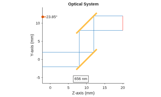
To add a mirror component to the optical system, use the addMirror function. Specify a tilt angle, using the TiltAngle name-value argument, that tilts the flat mirror 45 degrees clockwise along the x-direction. Specify the center thickness of the mirror, in millimeters, using the DistanceToNext name-value argument. The function automatically adds the specified 10 millimeter gap along the reflected optical axis, which now reflects in the positive y-direction (upwards).
addMirror(opsys,SemiDiameter=4,TiltAngles=45,DistanceToNext=10)
Add another mirror with a tilt angle of the new mirror such that the rays travel parallel to the positive z-axis. This tilt angle is -45 degrees counterclockwise relative to the positive x- axis, starting from the upward-oriented optical axis.
addMirror(opsys,SemiDiameter=4,TiltAngles=-45)
Add a gap between the mirror and the next optical component using the addGap object function.
addGap(opsys,10)
Add an image plane using the addImagePlane object.
addImagePlane(opsys,SemiDiameter=2)
Trace marginal rays through the optical system using the traceMarginalRays function, and display the optical system in 2-D using the view2d function. Add the traced rays to the visualization by using the addRays function.
hv = view2d(opsys); mr = traceMarginalRays(opsys,Wavelengths=656.261); addRays(hv,mr)
Input Arguments
Optical system to which to add the mirror as the next component, specified
as an opticalSystem object.
Name-Value Arguments
Specify optional pairs of arguments as
Name1=Value1,...,NameN=ValueN, where Name is
the argument name and Value is the corresponding value.
Name-value arguments must appear after other arguments, but the order of the
pairs does not matter.
Example: addMirror(SemiDiameter=3.0) specifies the semi-diameter
of the mirror as 3.0 millimeters.
Radius of curvature of the mirror, specified as one of these options:
| Input Type | Description |
|---|---|
| Numeric scalar | Radius of curvature applied uniformly to both
the x and y
directions. By default, the radius of curvature is
|
| 2-element row vector | Radius of curvature for a biconic surface, specified as [Rx, Ry], where Rx and Ry are the radii of curvature in the x and y directions, respectively. |
Aspheric coefficients of the mirror, specified as a 20-element row
vector. The aspheric coefficients describe the aspheric profile of the
mirror. By default, both even-powered and odd-powered aspheric
coefficients are equal to zero, and the mirror is a purely conic section
without any higher-order deviations. The conic surface shape depends on
the magnitude and sign of the conic constant specified by the
ConicConstant name-value argument.
Mirror optical coating, specified as an opticalCoating object. The
addMirror function applies the coating to the
front of the mirror surface where incident rays hit. By default, the
coating is a single 200 nm layer of silver (Ag).
Mirror substrate material, specified as an opticalMaterial object. By default, the substrate
material is SiO2.
Even-powered aspheric coefficients of the mirror, specified as a 10-element row vector.
Conic constant that defines the conic shape of the mirror, specified as one of these options:
| Input Type | Description |
|---|---|
| Numeric scalar | Conic constant, K, applied uniformly to both the x and y directions. |
| 2-element row vector | Conic constant for a biconic surface, specified as [Kx, Ky], where Kx and Ky are the conic constants in the x and y directions, respectively. |
Depending on the value of the conic constant K, the aspheric mirror surface has these conic shapes.
ConicConstant
(K) Value | Conic Shape |
|---|---|
K =
| Sphere |
K in range | Ellipse |
K =
| Parabola |
K in range | Hyperbola |
Normalization radius, specified as a positive scalar. The
addMirror function uses the normalization
radius to non-dimensionalize the higher-order terms in the polynomial
describing the aspheric mirror surface.
Mirror semi-diameter, in millimeters, specified as a positive scalar. The semi-diameter is the distance, along the positive y axis, from the center of the mirror to the edge of the usable optical area. This quantity is half the full diameter of the mirror.
Note
For a rectangular mirror, use the
RectangleSize name-value argument to
specify the mirror surface size, instead.
Additional Z-sag values on a regular grid, specified as an
M-by-N matrix. Units are in
millimeters. M is the number of y
samples spanning GridYLims, and N
is the number of x samples spanning
GridXLims.
The addMirror function adds these grid values to
the existing surface sag value. Positive values move the surface towards
the positive z direction and negative values move the
surface towards the negative z direction from the
baseline that the function computes using the Radius,
ConicConstant, and aspheric term arguments in
local surface coordinates. The function interpolates grid values using
bicubic interpolation and extrapolates values near the edges.
The element Grid(1,1) corresponds to the corner at
(GridYLims(1),
GridXLims(1)), which is the minimum
y- and minimum x-position of
the grid. The element Grid(1,end) corresponds to
(GridYLims(1),
GridXLims(2)), and Grid(end,end)
corresponds to (GridYLims(2),
GridXLims(2)), which is the maximum
y- and maximum x-position of
the grid. Row index increases with y, and column
index increases with x.
Data Types: double
X-limits of the grid edges in local surface coordinates, in millimeters, specified as a 2-element row vector. The vector is of the form [xmin, xmax], where xmin and xmax are the minimum and maximum x-coordinates of the grid, respectively. The second element must be greater than the first. By default, the limits are [-sd, +sd] for circular shapes and [-w/2, +w/2] for rectangular shapes, where sd is the semi-diameter and w is the width of the rectangular surface. The function ignores grid values that extend outside the surface shape. Valid regions of the surface not included in these limits use a grid value of 0.
Data Types: double
Y-limits of the grid edges in local surface coordinates, in millimeters, specified as a 2-element row vector. The vector is of the form [ymin, ymax], where ymin and ymax are the minimum and maximum y-coordinates of the grid, respectively. The second element must be greater than the first. By default, the limits are [-sd, +sd] for circular shapes and [-h/2, +h/2] for rectangular shapes, where sd is the semi-diameter and h is the height of the rectangular surface. The function ignores grid values that extend outside the surface shape. Valid regions of the surface not included in these limits use a grid value of 0.
Data Types: double
Version History
Introduced in R2026aYou can now specify separate radii of curvature and conic constants in the
x and y directions for biconic surfaces by
using the Radius and ConicConstant
name-value arguments, respectively.
You can now specify additional Z-sag values on a regular grid to add to the surface
sag baseline by using the Grid,
GridXLims, and GridYLims name-value
arguments.
See Also
opticalSystem | Mirror | addRefractiveSurface | addDiaphragm | addImagePlane
MATLAB Command
You clicked a link that corresponds to this MATLAB command:
Run the command by entering it in the MATLAB Command Window. Web browsers do not support MATLAB commands.
Seleccione un país/idioma
Seleccione un país/idioma para obtener contenido traducido, si está disponible, y ver eventos y ofertas de productos y servicios locales. Según su ubicación geográfica, recomendamos que seleccione: .
También puede seleccionar uno de estos países/idiomas:
Cómo obtener el mejor rendimiento
Seleccione China (en idioma chino o inglés) para obtener el mejor rendimiento. Los sitios web de otros países no están optimizados para ser accedidos desde su ubicación geográfica.
América
- América Latina (Español)
- Canada (English)
- United States (English)
Europa
- Belgium (English)
- Denmark (English)
- Deutschland (Deutsch)
- España (Español)
- Finland (English)
- France (Français)
- Ireland (English)
- Italia (Italiano)
- Luxembourg (English)
- Netherlands (English)
- Norway (English)
- Österreich (Deutsch)
- Portugal (English)
- Sweden (English)
- Switzerland
- United Kingdom (English)