traceAimedRay
R2026bDescription
Add-On Required: This feature requires the Optical Design and Simulation Library for Image Processing Toolbox add-on.
rayBundle = traceAimedRay(opsys,Name=Value)TargetSurfaceIndex=10 aims the ray at surface 10 in the
optical system.
Examples
Load a double Gauss lens from a ZMX file into the workspace.
opsys = zmximport("DoubleGaussLens.zmx");Specify the field point from which to trace an aimed ray.
opsys.FieldPoints(1) = fieldPoint(Position=[0 -10 0]);
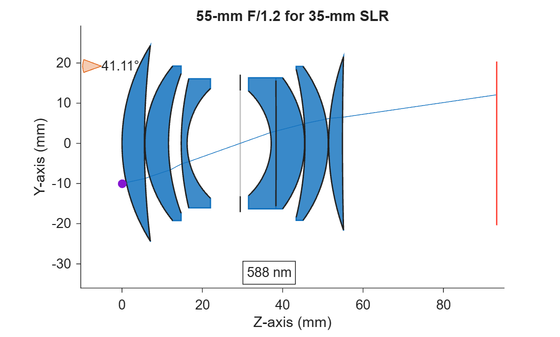
Trace an aimed ray from the field point.
rbt = traceAimedRay(opsys);
Display the optical system and the traced ray in 2-D.
hv = view2d(opsys);
addRays(hv,rbt);
Input Arguments
Optical system through which to trace the aimed ray, specified as an opticalSystem object.
Name-Value Arguments
Specify optional pairs of arguments as
Name1=Value1,...,NameN=ValueN, where Name is
the argument name and Value is the corresponding value.
Name-value arguments must appear after other arguments, but the order of the
pairs does not matter.
Example: traceAimedRay(opsys,TargetSurfaceIndex=10,TargetSurfacePoint=[0 12])
aims the ray at the point (0, 12) on surface 10.
Field point from which to start tracing the ray, specified as one of these options:
FieldPoint value | Light Source Type |
|---|---|
Array of | Field points represent light sources that are at an infinite distance from the first surface of the optical system. |
Array of | Field points represent light sources that are at a finite distance from the first surface of the optical system. |
Array of FieldPosition and FieldAngle
objects | Field points represent two types of light sources, either at an infinite distance or at a finite distance from the first surface of the optical system. |
To specify light source representations, create field points or arrays of field
points using the fieldPoint
function.
Index of the surface containing the target point, specified as a positive integer. The value must be between 1 and the number of surfaces in the optical system.
The default is the index of the first diaphragm (aperture stop) surface. If the optical system does not have a physical diaphragm, the default is 1.
Point on the target surface at which the ray is aimed, specified as a two-element numeric vector of the form [x, y], where x and y are the local coordinates of the surface. Specifying the point in local coordinates enables you to define the target relative to the surface, independent of its global position or tilt.
Wavelength at which to trace the ray, specified as a positive scalar in nanometers.
Additional ray properties to compute, specified as a string scalar, string array, character vector, or cell array of character vectors with one or more of these values.
The traceAimedRay function returns the specified ray properties
as additional fields in the RayData property of rayBundle. Each value
of RayProperties, except "All", creates a
field of the same name in RayData.
RayProperties Value | Field Value in RayData |
|---|---|
| Fresnel reflection and transmission coefficients at each interface, bulk transmission and phase shift, and the total transmittance through the optical system, represented as a structure with these fields.
|
| Polarization transformation matrices for each ray and surface intersection, represented as a structure with these fields.
|
| Adds all additional ray properties to
|
Data Types: string | char | cell
Output Arguments
Traced ray result, returned as a RayBundle
object.
Version History
Introduced in R2026b
See Also
traceDirectedRays | traceChiefRay | traceRays | traceMarginalRays | opticalSystem
MATLAB Command
You clicked a link that corresponds to this MATLAB command:
Run the command by entering it in the MATLAB Command Window. Web browsers do not support MATLAB commands.


Seleccione un país/idioma
Seleccione un país/idioma para obtener contenido traducido, si está disponible, y ver eventos y ofertas de productos y servicios locales. Según su ubicación geográfica, recomendamos que seleccione: .
También puede seleccionar uno de estos países/idiomas:
Cómo obtener el mejor rendimiento
Seleccione China (en idioma chino o inglés) para obtener el mejor rendimiento. Los sitios web de otros países no están optimizados para ser accedidos desde su ubicación geográfica.
América
- América Latina (Español)
- Canada (English)
- United States (English)
Europa
- Belgium (English)
- Denmark (English)
- Deutschland (Deutsch)
- España (Español)
- Finland (English)
- France (Français)
- Ireland (English)
- Italia (Italiano)
- Luxembourg (English)
- Netherlands (English)
- Norway (English)
- Österreich (Deutsch)
- Portugal (English)
- Sweden (English)
- Switzerland
- United Kingdom (English)