axesmui
Define axesm-based map and modify projection and display
properties
Activation
Command Line | Map Display |
|---|---|
|
|
Description
axesmui activates a Projection Control dialog box for the current
axesm-based map. The dialog box allows map projection
definition and property modification.
c is an optional output argument that indicates whether the
Projection Control dialog box was closed by the cancel button. c = 1
if the cancel button is pushed. Otherwise, c = 0.
Extend-clicking a map display brings up the Projection Control dialog box for that
axesm-based map.
Controls
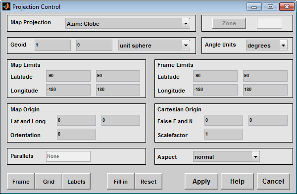
The Map Projection pull-down menu is used to select a map projection. The projections are listed by type, and each is preceded by a four-letter type indicator:
Cyln = Cylindrical
Pcyl = Pseudocylindrical
Coni = Conic
Poly = Polyconic
Pcon = Pseudoconic
Azim = Azimuthal
Mazi = Modified Azimuthal
Pazi = Pseudoazimuthal
The Zone button and edit box are used to specify a zone for the Universal Transverse Mercator (UTM) and Universal Polar Stereographic (UPS) projections.
Note
The Zone button and edit box are not supported in
MATLAB®
Online™. Programmatically create an axesm-based map
instead. For example, create an axesm-based map using a UTM
projection by specifying the MapProjection and
Zone name-value pairs:
ax = axesm('MapProjection','UTM','Zone','54S');
The Geoid edit boxes and pull-down menu are used to specify the geoid. Units must be in meters for the UTM and UPS projections, since this is the standard unit for the two projections. For non-UTM and UPS projections, the geoid unit can be anything, bearing in mind that the resulting projected data will be in the same units as the geoid.
The Angle Units pull-down menu is used to specify the angle units used on the map projection. All angle entries corresponding to the current map projection must be entered in these units. Current angle entries are automatically updated when new angle units are selected.
The Map Limits edit boxes are used to specify the extent of the map data in geographic coordinates. The Latitude edit boxes contain the southern and northern limits of the map. The Longitude edit boxes contain the western and eastern limits of the map. The map limits establish the extent of the meridian and parallel grid lines, regardless of the display settings (see grid settings). Map limits are always in geographic coordinates, regardless of the map origin and orientation setting. In the normal aspect, the map display is trimmed to the minimum of the map and frame limits.
The Frame Limits edit boxes are used to specify the
location of the map frame, measured from the center of the map projection in the base
coordinate system. The Latitude edit boxes contain the
southern and northern frame edge locations. The Longitude edit boxes contain the western and eastern frame edge
locations. Displayed map data are trimmed at the frame limits. For azimuthal map
projections, the latitude limits should be set to –inf and the
desired trim distance from the map origin. In the normal aspect, the map display is
trimmed to the minimum of the map and frame limits.
The Map Origin edit boxes are used to specify the origin and aspect angle of the map projection. The Lat and Long boxes specify the map origin in geographic coordinates. This is the point that is placed in the center of the projection. If either box is left blank, 0 degrees is used. The Orientation box specifies the azimuth angle of the North Pole relative to the map origin. Azimuth is measured clockwise from the top of the projection. If the Orientation box is disabled, then the selected map projection requires a fixed orientation. See the Mapping Toolbox User's Guide for a complete description of the map origin.
The Cartesian Origin edit boxes are used to specify the x-y offset, along with a desired scale factor of the map projection. The False E and N boxes specify the false easting and northing in Cartesian coordinates. These must be in the same units as the geoid. The Scalefactor box specifies the scale factor used in the map projection calculations.
The Parallels edit boxes specify the standard parallels of the selected map projection. A particular map projection may have one or two standard parallels. If the edit boxes are disabled, then the selected projection has no standard parallels or the standard parallels are fixed.
The Aspect pull-down menu is used to select a normal
or transverse display aspect. When the aspect is normal, north (on
the base projection) is up, and the map is displayed in a portrait
setting. In a transverse aspect, north (in the base projection) is to the right, and the
map is displayed in a landscape setting. This property does not
control the map projection aspect. The projection aspect is determined by the map
Origin property).
The Frame button brings up the Map Frame Properties dialog box, which allows the map frame settings to be modified.
The Grid button brings up the Map Grid Properties dialog box, which allows the map grid settings to be modified.
The Labels button brings up the Map Label Properties dialog box, which allows the parallel and meridian label settings to be modified.
The Fill in button is used to compute projection and display settings based on any currently specified map parameters. Only settings that are left blank are affected when this button is pushed.
The Reset button is used to reset the default projection
properties and display settings of the current map. Default display settings include
frame, grid, and label properties set to 'off'.
The Apply button is used to apply the projection and display settings to the current map, which results in the map being reprojected.
The Help button is used to bring up online help text for each control on the Projection Control dialog box.
The Cancel button disregards any modified projection or display settings and closes the Projection Control dialog box.
Map Frame Properties Dialog Box
This dialog box allows modification of the map frame settings. It is accessed via the Frame button on the Projection Control dialog box.
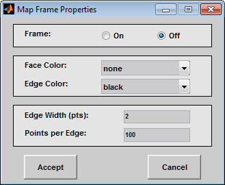
The Frame selection buttons determine whether the map frame is visible.
The Face Color pull-down menu is used to select
the background color of the map frame. Selecting none results in
a transparent frame background, i.e., the same as the axes color. Selecting
custom allows a custom RGB triple to be defined for the
background color.
The Edge Color pull-down menu is used to select
the color of the frame edge. Selecting none hides the frame edge.
Selecting custom allows a custom RGB triple to be defined for the
edge color.
The Edge Width edit box is used to enter the line width of the frame edge, in points.
The Points per Edge edit box is used to enter the number of points used to display each edge of the map frame.
The Accept button accepts any modifications made to the map frame properties and returns to the Projection Control dialog box. Changes are applied to the current map only when the Apply button on the Projection Control dialog box is pushed.
The Cancel button disregards any modifications to the map frame properties and returns to the Projection Control dialog box.
Map Grid Properties Dialog Box
This dialog box allows modification of the map frame settings. It is accessed via the Grid button on the Projection Control dialog box.
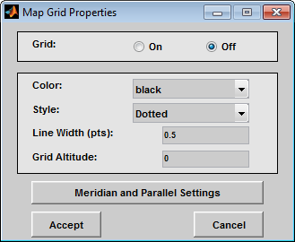
The Grid selection buttons determine whether the map grid is visible.
The Color pull-down menu is used to select the
color of the map grid lines. Selecting custom allows a custom RGB
triple to be defined for the grid line color.
The Style pull-down menu is used to select the line style of the map grid lines.
The Line Width edit box is used to enter the width of the map grid lines, in points.
The Grid Altitude edit box is used to enter
z-axis location of the map grid. This property can be used
to place some mapped objects above or below the map grid. The default map grid
altitude is inf, which places the grid above all other mapped
objects.
The Meridian and Parallel Settings button brings up the Meridian and Parallel Properties dialog box, which allows the properties of the meridian and parallel grid lines to be modified.
The Accept button accepts any modifications made to the map grid properties and returns to the Projection Control dialog box. Changes are applied to the current map only when the Apply button on the Projection Control dialog box is pushed.
The Cancel button disregards any modifications to the map grid properties and returns to the Projection Control dialog box.
Meridian and Parallel Properties Dialog Box
This dialog box is used to modify the settings for meridian and parallel grid lines. It is accessed via the Meridian and Parallel Settings button on the Map Grid Properties dialog box.
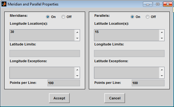
The Meridians selection buttons determine whether the meridian grid lines are visible when the map grid is turned on.
The Longitude Location(s) edit box is used to specify which meridians are to be displayed if the meridian lines are turned on. If a scalar interval value is entered, meridian lines are displayed at that interval, starting from the Prime Meridian and proceeding in east and west directions. If a vector of values is entered, meridian lines are displayed at locations given by each element of the vector.
The Latitude Limits edit box is used to specify the latitude limits beyond which meridian lines do not extend. If this property is left empty, all meridian lines extend to the map latitude limits (specified by the Latitude Map Limits entry on the Projection Control dialog box). This entry must be a two-element vector enclosed in brackets.
The Longitude Exceptions edit box is used to enter specific meridians of the displayed grid that are to extend beyond the latitude limits, to the map limits. This entry is a vector of longitude values.
The Parallels selection buttons determine whether the parallel grid lines are visible when the map grid is turned on.
The Latitude Location(s) edit box is used to specify which parallels are to be displayed if the parallel lines are turned on. If a scalar interval value is entered, parallel lines are displayed at that interval, starting from the Equator and proceeding in north and south directions. If a vector of values is entered, parallel lines are displayed at locations given by each element of the vector.
The Longitude Limits edit box is used to specify the longitude limits beyond which parallel lines do not extend. If this property is left empty, all parallel lines extend to the map longitude limits (specified by the Longitude Map Limits entry on the Projection Control dialog box). This entry must be a two-element vector enclosed in brackets.
The Latitude Exceptions edit box is used to enter specific parallels of the displayed grid that are to extend beyond the longitude limits, to the map limits. This entry is a vector of latitude values.
The Points per Line edit boxes are used to enter the number of points used to plot each meridian and each parallel grid line. The default value is 100 points.
The Accept button accepts any modifications that have been made to the meridian and parallel grid line properties and return to the Map Grid Properties dialog box. Changes are applied to the current map only when the Apply button on the Projection Control dialog box is pushed.
The Cancel button disregards any modifications to the meridian and parallel grid lines and returns to the Map Grid Properties dialog box.
Map Label Properties Dialog Box
This dialog box is used to modify the settings of the meridian and parallel labels. It is accessed via the Label button on the Projection Control dialog box.
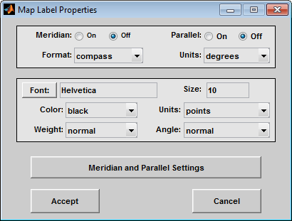
The Meridian and Parallel selection buttons determine whether the meridian and parallel labels are visible.
The Format pull-down menu is used to specify the
format of the grid labels. If compass is selected, meridian
labels are appended with E for east and W for
west, and parallel labels are appended with N for north and
S for south. If signed is chosen, meridian
labels are prefixed with + for east and - for
west, and parallel labels are prefixed with + for north and
- for south. If none is selected, western
meridian labels and southern parallel labels are prefixed by -,
but no symbol precedes eastern meridian labels and northern parallel labels.
The label Units pull-down menu is used to specify the angle units used to display the parallel and meridian labels. These units, used for display purposes only, need not be the same as the angle units of the map projection.
The Font edit box is used to specify the
character font used to display the parallel and meridian labels. If the font
specified does not exist on the computer, the default of
Helvetica is used. Pressing the Font button previews the selected font.
The font Size edit box is used to enter an integer value that specifies the font size of the parallel and meridian labels. This value must be in the units specified by the font Units pull-down menu.
The font Color pull-down menu is used to select
the color of the parallel and meridian labels. Selecting custom
allows a custom RGB triple to be defined for the labels.
The font Weight pull-down menu is used to specify the character weight of the parallel and meridian labels.
The font Units pull-down menu is used to specify
the units used to interpret the font size entry. When set to
normalized, the value entered in the Size edit box is interpreted as a fraction of the height of the
axes. For example, a normalized font size of 0.1 sets the label text to a height of
one tenth of the axes height.
The font Angle pull-down menu is used to select
the character slant of the parallel and meridian labels. normal
specifies nonitalic font. italic and oblique
specify italic font.
The Meridian and Parallel Settings button brings up the Meridian and Parallel Label Properties dialog box, which allows modification of properties specific to the meridian and parallel grid labels.
The Accept button accepts any modifications that have been made to the map label properties and returns to the Projection Control dialog box. Changes are applied to the current map only when the Apply button on the Projection Control dialog box is pushed.
The Cancel button disregards any modifications to the map labels and returns to the Projection Control dialog box.
Meridian and Parallel Label Properties Dialog Box
This dialog box is used to modify properties specific to the meridian and parallel grid labels. It is accessed via the Meridian and Parallel Settings button on the Map Label Properties dialog box.
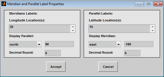
The Longitude Location(s) edit box is used to specify which meridians are to be labeled. Meridian labels need not coincide with displayed meridian grid lines. If a scalar interval value is entered, labels are displayed at that interval, starting from the Prime Meridian and proceeding in east and west directions. If a vector of values is entered, labels are displayed at longitude locations given by each element of the vector.
The Display Parallel pull-down menu and edit box
are used to specify the latitude location of the meridian labels. If a scalar
latitude value is provided in the edit box, the meridian labels are placed at that
parallel. Alternatively, the pull-down menu can be used to select a latitude
location. If north is chosen, meridian labels are placed at the
maximum map latitude limit. If south is chosen, meridian labels
are placed at the minimum map latitude limit.
The Latitude Location(s) edit box is used to specify which parallels are to be labeled. Parallel labels need not coincide with displayed parallel grid lines. If a scalar interval value is entered, labels are displayed at that interval, starting from the Equator and proceeding in north and south directions. If a vector of values is entered, labels are displayed at latitude locations given by each element of the vector.
The Display Meridian pull-down menu and edit box
are used to specify the longitude location of the parallel labels. If a scalar
longitude value is provided in the edit box, the parallel labels are placed at that
meridian. Alternatively, the pull-down menu can be used to specify a longitude
location. If east is chosen, parallel labels are placed at the
maximum map longitude limit. If west is chosen, parallel labels
are placed at the minimum map longitude limit.
The Decimal Round edit boxes are used to specify the power of ten to which the meridian and parallel labels are rounded. For example, a value of -1 results in labels displayed to the tenths decimal place.
The Accept button accepts any modifications that have been made to the meridian and parallel label properties and return to the Map Label Properties dialog box. Changes are applied to the current map only when the Apply button on the Projection Control dialog box is pushed.
The Cancel button disregards any modifications to the meridian and parallel labels and returns to the Map Label Properties dialog box.
The Map Geoid edit box is used to specify the
geoid (ellipsoid) definition for the current axesm-based map.
The geoid is defined by a two-element vector of the form [semimajor-axis
eccentricity]. Eccentricity must be a value between 0 and 1, but not
equal to 1. A nonzero eccentricity represents an ellipsoid. The default geoid is a
sphere with radius 1, represented as [1 0]. If a scalar entry is
provided, it is assumed to be the radius of a sphere.
The Accept button accepts any modifications that have been made to the map geoid and return to the Projection Control dialog box. Changes are applied to the current map only when the Apply button on the Projection Control dialog box is pushed.
The Cancel button disregards any modifications to the map geoid and returns to the Projection Control dialog box.
Version History
Introduced in R2007a