Per-Unit System
Motor Control Blockset™ uses these International System of Units (SI):
| Quantity | Unit | Symbol |
|---|---|---|
| Voltage | volt | V |
| Current | ampere | A |
| Speed | radians per second revolutions per minute | rad/s rpm |
| Torque | newton-meter | N.m |
| Power | watt | W |
Note
The SI Unit for speed is rad/s. However, most manufacturers use rpm as the unit to specify the rotational speed of the motors. Motor Control Blockset prefers rpm as the unit of rotational speed over rad/s. However, you can use either value based on your preference.
Per-Unit System
The per-unit (PU) system is commonly used in electrical engineering to express the values of quantities like voltage, current, power, and so on. It is used for transformers and AC machines for power system analysis. Embedded systems engineers also use this system for optimized code-generation and scalability, especially when working with fixed-point targets.
For a given quantity (such as voltage, current, power, speed, and torque), the PU system expresses a value in terms of a base quantity:
Generally, most systems select the nominal values of the system as the base values. Sometimes, a system may also select the maximum measurable value as the base value. After you establish the base values, all signals are represented in PU with respect to the selected base value.
For example, in a motor control system, if the selected base value of the current is 10A, then the PU representation of a 2A current is expressed as (2/10) PU = 0.2 PU.
Similarly,
For example, the SI unit representation of 0.2 PU = (0.2 x base value) = (0.2 x 10) A.
Per-Unit System and Motor Control Blockset
Motor Control Blockset uses these conventions to define the base values for voltage, current, speed, torque, and power.
| Quantity | Representation | Convention |
|---|---|---|
| Base voltage | Vbase | This is the maximum phase voltage supplied by the inverter. Generally, for Space Vector PWM, it is . For Sinusoidal PWM, it is . For discontinuous PWM (DPWM), it is . For more information about the PWM techniques, see PWM Reference Generator. |
| Base current | Ibase | This is the maximum current that can be measured by the current sensing circuit of the inverter. Generally, but not necessarily, it is ISenseMax of the inverter. |
| Base speed | Nbase | This is the nominal (or rated) speed of the motor. This is also the maximum speed that the motor can achieve at the nominal voltage and nominal load without a field-weakening operation. |
| Base torque | Tbase | This torque is mathematically derived from the base current. Physically, the motor may or may not be able to produce this torque. Generally, it is . |
| Base power | Pbase | This is the power derived by the base voltage and base current. Generally, it is . |
where:
Vdc is the DC voltage that you provide to the inverter.
Imax is the maximum current measured by the ADCs connected to the current sensors of the inverter.
p is the number of pole pairs available in the PMSM.
FluxPM is the permanent magnet flux linkage of the PMSM.
pmsm is the MATLAB® workspace parameter structure that saves the motor variables.
inverter is the MATLAB workspace parameter structure that saves the inverter variables.
PU_System is the MATLAB workspace parameter structure that saves the PU system variables.
For the voltage and current values, you can generally consider the peak value of the nominal sinusoidal voltage (or current) as 1PU. Therefore, the base values used for voltage and current are the RMS values multiplied by , or the peak value measured between phase-neutral.
You can simplify your calculations by using the PU system. Motor Control Blockset uses these base value definitions for the PU-system-related
conversions performed by the algorithms used in the toolbox examples. The toolbox
stores the PU-system-related variables in a structure called
PU_System in the MATLAB workspace.
Why Use Per-Unit System Instead of Standard SI Units
Per-unit representation of signals has many advantages over the SI units. This technique:
Improves the computational efficiency of code execution, and therefore is a preferred system for fixed-point targets.
Creates a scalable control algorithm that can be used across many systems.
Convert SI Units to Per-Unit System for Field-Oriented Control
This example shows how to convert from SI units to the per-unit (PU) system for field-oriented control of a PMSM.
Prepare and Simulate Model in SI Units
Run the script FOCofPMSMData to load parameters to the base workspace. Notice that the ControllerVariant variable is set to SI in the script, which selects the SI Unit Control variant for the Control subsystem.
FOCofPMSMData;
Open and simulate the example model. Open the Data Inspector and observe the field oriented control operation in SI units (rad/s).
mdl = "FOCofPMSM";
open_system(mdl);
sim(mdl);
Simulink.sdi.view;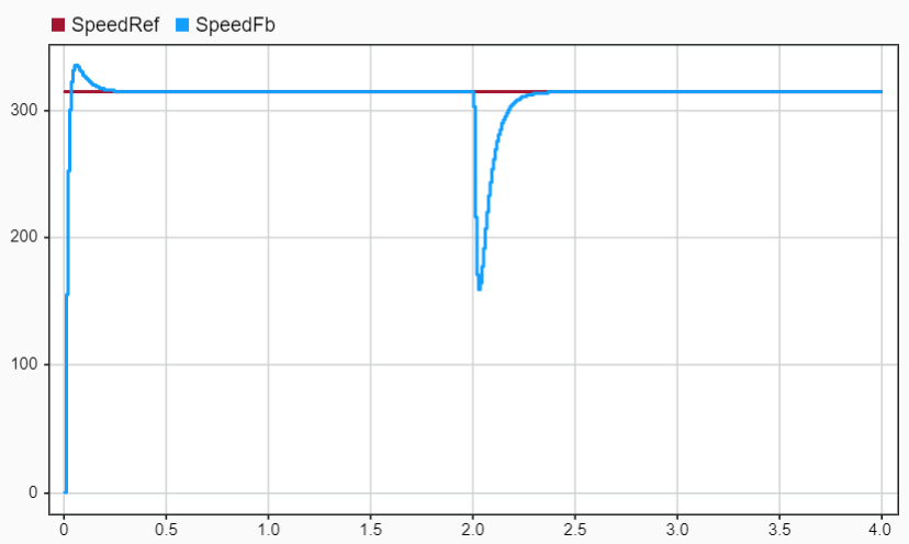
Convert Model to Per-Unit System
Set up the per-unit system by computing base values.
PU_System = mcb.getPUSystemParameters(pmsm,inverter);
Configure the Per Unit Control variant for the Control subsystem by setting the ControllerVariant variable to PU. You can switch to the SI Unit Control variant at any time by re-assigning the variable to SI or by running the FOCofPMSMData script.
ControllerVariant = 'PU';Examine Per Unit Control Subsystem
Examine the Per Unit Control subsystem. Highlight blocks that convert signals to per-unit values, or blocks with parameters configured to per-unit values.
Use the convert2PU block to convert the input reference speed to per-unit values.
hilite_system('FOCofPMSM/Control/Per Unit Control/Speed Controller/convert2PU');Update the feedback system to per-unit values:
Use the
Convert2PUblock to convert the input current feedback to per-unit values.Use the
ConvertTheta2PUblock to convert the measured motor position to per-unit values.In the
Mechanical to Electrical Positionblock, set Input angle mechanical unit toPer unit.In the
Speed Measurementblock, set Position unit toPer unit, and Speed unit toPer unit based on dialog.
hilite_system('FOCofPMSM/Control/Per Unit Control/Current Controller/Convert2PU');
hilite_system('FOCofPMSM/Control/Per Unit Control/Current Controller/ConvertTheta2PU');
hilite_system('FOCofPMSM/Control/Per Unit Control/Current Controller/Mechanical to Electrical Position');
hilite_system('FOCofPMSM/Control/Per Unit Control/Current Controller/Speed Measurement');
In the Field-Oriented Current Controller block, set Input electrical position unit to Per-unit. This enables the Sine-Cosine Lookup block inside to accept position inputs in per-unit values.
hilite_system('FOCofPMSM/Control/Per Unit Control/Current Controller/Field-Oriented Current Controller','green');
Update the PI controller configuration by setting its limits to -1 and 1.
hilite_system('FOCofPMSM/Control/Per Unit Control/Current Controller/Constant2','red');
Since the current controller output is saturated from -1 to +1, use the Convert2Voltages block to scale the Vabc output to actual voltages to feed to the motor plant.
hilite_system('FOCofPMSM/Control/Per Unit Control/Current Controller/Convert2Voltages','blue');
In the SpeedController block, update the saturation limits to per-unit values. Set Upper limit to pmsm.I_rated/PU_System.I_base and Lower limit to -pmsm.I_rated/PU_System.I_base.
hilite_system('FOCofPMSM/Control/Per Unit Control/Speed Controller/SpeedController');In the FOC Default Controller Gains block, set Output unit to Per-unit. This block requires base speed and base current inputs to compute PI controller gains in per-unit values.
hilite_system('FOCofPMSM/Control/Per Unit Control/Tune PI Controllers/FOC Default Controller Gains');Simulate Model in Per-Unit System
Simulate the model. Open the Data Inspector and observe the field oriented control operation in the per-unit system.
sim(mdl);
Simulink.sdi.view;
When comparing plots in SI units (left) and per-unit system (right), notice that the controller responses in both unit systems are identical.


See Also
Topics
- Per-Unit System of Units (Simscape Electrical)