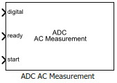
ADC AC Measurement
Measure AC performance metrics of ADC output
Libraries:
Mixed-Signal Blockset /
ADC /
Measurements & Testbenches
Description
The ADC AC Measurement block measures ADC AC performance metrics such as signal to noise ratio (SNR), signal to noise and distortion radio (SINAD), spurious free dynamic range (SFDR), effective number of bits (ENOB), noise floor, and conversion delay. You can use ADC AC Measurement block to validate the ADC architectural models provided in Mixed-Signal Blockset™, or you can use an ADC of your own implementation
Ports
Input
Converted digital signal from an ADC, specified as a scalar.
Data Types: fixed point | single | double | int8 | int16 | int32 | uint8 | uint16 | uint32
Indicates whether the analog to digital conversion is complete, specified as a scalar.
Data Types: double
External conversion start clock, specified as a scalar. The analog to digital conversion process starts at the rising edge of the signal at the start port.
Data Types: double
Parameters
Type of distortion the ADC AC Measurement block is set to measure,
specified as Harmonic or
Intermodulation.
Programmatic Use
Block parameter:
DistortionMeasurement |
| Type: character vector |
Values:
Harmonic |
Intermodulation |
Default:
Harmonic |
Frequency of the analog input signal to an ADC block, specified as a positive real scalar or positive real valued vector in hertz. Analog stimulus frequency must match the input frequency to the ADC device under test.
When the ADC AC Measurement is set to measure the
Harmonicdistortion, the default value of Analog stimulus frequency is10000.When the ADC AC Measurement is set to measure the
Intermodulationdistortion, the default value of Analog stimulus frequency is[9000,11000].
Analog stimulus frequency must not share any common multiples other than 1 with the Start conversion frequency.
To satisfy this condition, use the equation ,
where:
fanalog is the analog signal frequency,
fstart is the start conversion frequency,
J is the number of cycles of the stimulus per FFT window,
and M is the number of FFT points.
Note
J is selected as the largest prime number less than one tenth of the number of FFT points. The minimum value of M is allowed to be 16.
Programmatic Use
Block parameter:
InputFrequency |
| Type: character vector |
| Values: positive real scalar | positive real valued vector |
Default:
10000 |
Select the spectrum estimation method as one of the following:
Filter bank — Use an analysis filter bank to estimate the power spectrum. Compared to Welch's method, this method has a lower noise floor, better frequency resolution, lower spectral leakage, and requires fewer samples per update. For more information, see Spectrum Estimation — Filter Bank
Welch — Use Welch's method of averaged modified periodograms. For more information, see Spectrum Estimation — Welch's Method
Programmatic Use
Block parameter:
Method |
| Type: character vector |
| Values: Filter bank | Welch |
| Default: Filter bank |
Resolution bandwidth, specified as a positive real scalar in hertz. This parameter defines the smallest positive frequency that can be resolved. By default, this parameter is calculated automatically. You can deselect Set automatically to customize the value.
Programmatic Use
Block parameter:
RBW |
| Type: character vector |
| Values: positive real scalar |
Default:
976.5625 |
Frequency of the start conversion clock of the ADC, specified as a positive real scalar in hertz. Start conversion frequency must match the frequency of the start conversion clock of the ADC block.
Programmatic Use
Block parameter:
Frequency |
| Type: character vector |
| Values: positive real scalar |
Default:
1e6 |
Delays measurement analysis to avoid corruption by transients, specified as a nonnegative real scalar in seconds.
Programmatic Use
Block parameter:
HoldOffTime |
| Type: character vector |
| Values: nonnegative real scalar |
Default:
0 |
Minimum time the simulation must run to obtain meaningful results, specified as a positive real scalar in seconds.
For AC measurement, the simulation must run so that the ADC can generate 6 spectral updates of the ADC output. The time to generate one spectral output based on Welch's method is given by:
where SamplingFrequency and RBW are the sampling frequency and resolution bandwidth of the spectrum estimator inside the ADC Testbench block.
This parameter is only reported by the testbench and is not editable.
Data Types: double
Click to automatically set the Recommended min. simulation stop time (s) as the stop time of the Simulink® model.
Store detailed test results in the base workspace for further processing at the end of simulation. By default, this option is not selected.
Name of the variable that stores detailed test results, specified as a character string.
Dependencies
This parameter is only available when Output result to base workspace is selected.
Programmatic Use
Block parameter:
VariableName |
| Type: character vector |
| Values: character string |
Default:
adc_ac_out |
Displays spectrum analyzer during simulation. By default, this option is not selected.
More About
Signal to noise ratio or SNR is the ratio of the RMS signal amplitude to the mean value of the root-sum-squares of all other spectral components, excluding the DC and first five harmonics.
Signal to noise and distortion ratio, or SINAD is the ratio of the RMS signal amplitude to the mean value of the root-sum-squares of all other spectral components and harmonics, excluding DC.
Spurious free dynamic range or SFDR is the ratio of the RMS signal amplitude to the RMS value of the peak spurious content, measured over the entire first Nyquist zone (DC to half of sampling frequency).
Effective number of bits or ENOB represents the actual resolution of an ADC after considering internal noise and errors. It is given by .
Version History
Introduced in R2019a
See Also
SAR ADC | Flash ADC | ADC Testbench | ADC DC Measurement | Spectrum Analyzer
MATLAB Command
You clicked a link that corresponds to this MATLAB command:
Run the command by entering it in the MATLAB Command Window. Web browsers do not support MATLAB commands.
Seleccione un país/idioma
Seleccione un país/idioma para obtener contenido traducido, si está disponible, y ver eventos y ofertas de productos y servicios locales. Según su ubicación geográfica, recomendamos que seleccione: .
También puede seleccionar uno de estos países/idiomas:
Cómo obtener el mejor rendimiento
Seleccione China (en idioma chino o inglés) para obtener el mejor rendimiento. Los sitios web de otros países no están optimizados para ser accedidos desde su ubicación geográfica.
América
- América Latina (Español)
- Canada (English)
- United States (English)
Europa
- Belgium (English)
- Denmark (English)
- Deutschland (Deutsch)
- España (Español)
- Finland (English)
- France (Français)
- Ireland (English)
- Italia (Italiano)
- Luxembourg (English)
- Netherlands (English)
- Norway (English)
- Österreich (Deutsch)
- Portugal (English)
- Sweden (English)
- Switzerland
- United Kingdom (English)