Measuring VCO Phase Noise to Compare with Target Profile
This example shows how to validate the phase noise profile of a VCO device under test (DUT) using a VCO Testbench.
Open the model vcoPhaseNoise. The model consists of a VCO block and a VCO Testbench.
open_system('vcoPhaseNoise.slx')
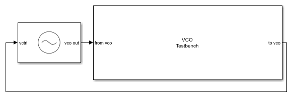
The voltage sensitivity of the VCO is set to 1.25e6 Hz, and the free running frequency is 2e9 Hz.
The testbencch is set to measure the Phase noise metric of the VCO in the Measurement option. The Control voltage provided to the input of VCO is 4 V. So, the VCO operates at 2.5 GHz frequency. Click the Autofill setup parameters button to automatically calculate the Resolution bandwidth (Hz), and No. of spectral averages.
Run simulation for 8e-4 s, as recommended in the Block Parameters dialog box. Double click the VCO Testbench block to open the Block Parameters dialog box. Click on the Plot measurement button.

The operating frequency matches the predicted frequency 2.5 GHz. The measured phase noise profile also matches the target profile.
Select a Web Site
Choose a web site to get translated content where available and see local events and offers. Based on your location, we recommend that you select: United States.
You can also select a web site from the following list
Americas
- América Latina (Español)
- Canada (English)
- United States (English)
Europe
- Belgium (English)
- Denmark (English)
- Deutschland (Deutsch)
- España (Español)
- Finland (English)
- France (Français)
- Ireland (English)
- Italia (Italiano)
- Luxembourg (English)
- Netherlands (English)
- Norway (English)
- Österreich (Deutsch)
- Portugal (English)
- Sweden (English)
- Switzerland
- United Kingdom (English)
Asia Pacific
- Australia (English)
- India (English)
- New Zealand (English)
- 中国
- 日本Japanese (日本語)
- 한국Korean (한국어)