Load-Flow Analyzer
Determine steady-state voltage magnitudes and angles and real and reactive power flows for three-phase AC, DC, or mixed AC/DC network
Description
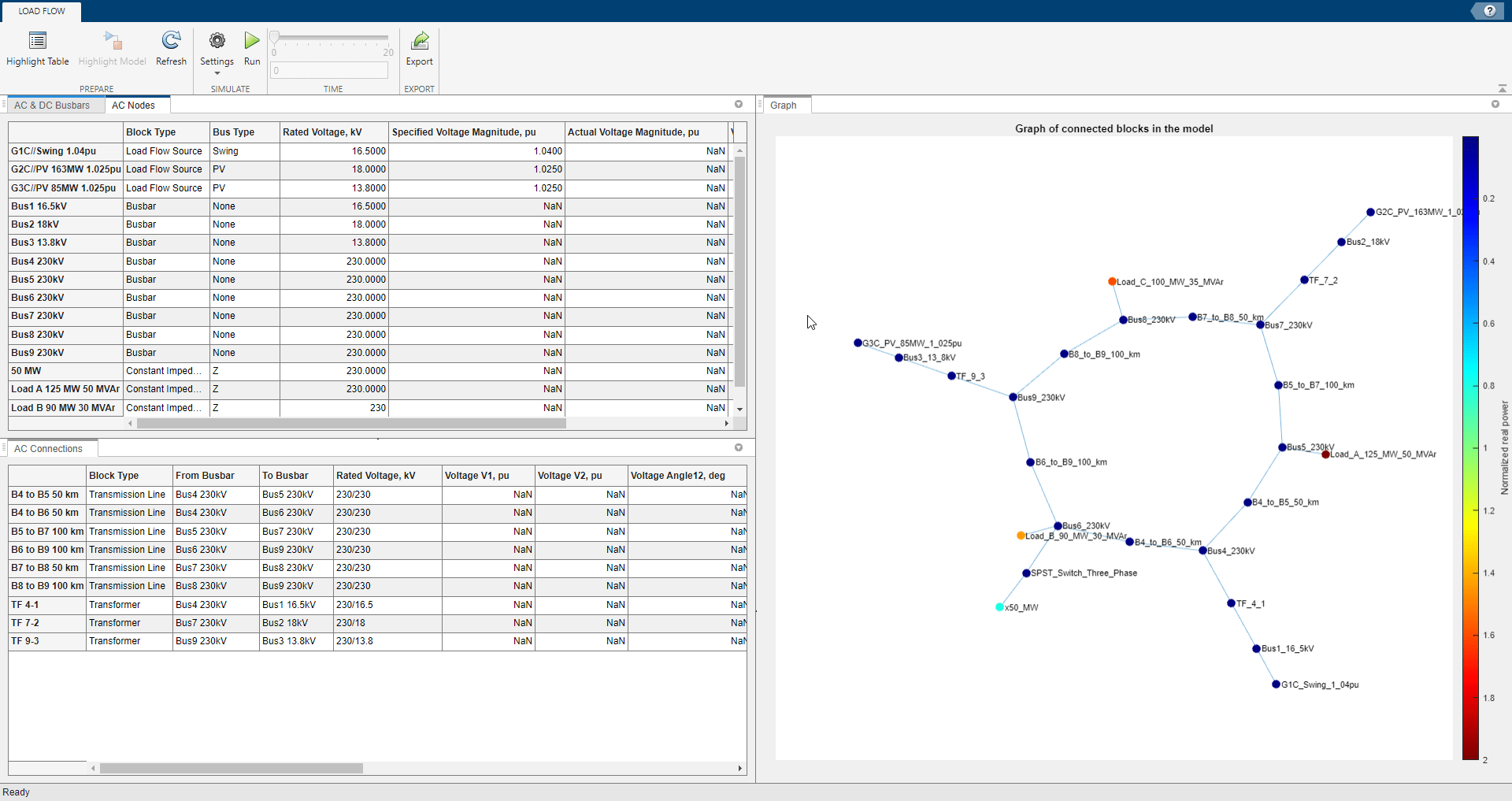
The Load-Flow Analyzer app performs a load-flow, or power-flow, analysis for a three-phase AC or DC electrical power transmission system that you model and configure for analysis using Simscape™ Electrical™. The app generates three tables. The AC Nodes table contains data for the AC network nodes, as represented by AC busbar, load flow source, synchronous machine, induction machine, and three-phase load blocks. The AC & DC Busbars table contains data for all busbars. The AC Connections table contains data for the network connections, as represented by transmission line and transformer blocks. The app also plots the nodes and connections of the system in a 2-D graph.
The Load-Flow Analyzer app allows you to:
Run a load-flow analysis.
Highlight and update load-flow input block parameter values for busbar, load flow source, synchronous machine, induction machine, and three-phase load blocks.
Change the bus type of load flow source, synchronous machine, and induction machine blocks.
Select and highlight node and connection blocks in the model.
Sort columns in the tables by increasing or decreasing values.
Export the data to a spreadsheet, a MAT-file, or comma-separated variable (CSV) files.
Visualize the connected blocks in a 2-D graph to check the input generators and loads inside the model and understand how the power flows across the network.
This table shows the available Simscape Electrical blocks that you can use to model the network nodes and connections:
Open the Load-Flow Analyzer App
Simulink® Toolstrip: On the Apps tab, under Simscape, click the Load-Flow Analyzer icon.
MATLAB® Command Window: To prepare to perform a power-flow analysis on the current
model, which is the open model that you most recently interacted with, enter
ee_loadFlowApp. To prepare for an analysis on an open model that is not
the current model, you must pass the model name as an input argument to the command.
When you open the app, the tables are preloaded with node and connection blocks and with
specified parameter values for the blocks in the current or specified model that are inputs to
the load-flow analysis. If the simulation has not yet been executed to generate the
corresponding Simscape Simulation Data object in the MATLAB base workspace, then the fields
for load-flow analysis output data contain NaN.
After you run the load-flow analysis, the tables also display the load-flow analysis output values, including the steady-state voltage magnitudes, voltage phase angles, active power, and reactive power for the node and connection blocks.
Examples
Open the model. At the MATLAB command prompt, enter:
ee_loadflow_ieee9bus
ee_loadflow_ieee9bus model is the current model.Open the Load-Flow Analyzer app.
ee_loadFlowApp
The Load-Flow Analyzer app opens and is preloaded with load-flow input
parameter values for applicable node and connection blocks in the
ee_loadflow_ieee9bus model.
Open the model. At the MATLAB command prompt, enter:
modelName = 'ee_loadflow_ieee9bus'
open_system(modelName)
Open the Load-Flow Analyzer app by passing the name of the model as an input argument.
ee_loadFlowApp(modelName)
The Load-Flow Analyzer app opens and is preloaded with load-flow input parameter values for applicable node and connection blocks in the specified model.
To identify load-flow analysis inputs that you can tune by updating values in the Load-Flow Analyzer app or block parameter settings, select Highlight Table.
To change the Bus Type for Load-Flow Source, wye-connected load, synchronous machine, or induction machine blocks, double-click the field for the bus type, and select an applicable type. Options are:
| Load-Flow Source | Synchronous Machine | Induction Machine | Wye-Connected Load | ||||
|---|---|---|---|---|---|---|---|
Time | Swing | PV | Z | ||||
Swing | PV | ||||||
PV | PQ | PQ | |||||
PQ | |||||||
To change a load-flow analysis input, update the applicable values in the Load-Flow Analyzer app or in the block parameter settings.
Note
If you update input values in the table, the values displayed in the block settings update immediately. However, if you update input values in the block settings or rewire the diagram, the values displayed in the table reflect the change only if you click the Refresh button in the Load-Flow Analyzer app.
If a parameter value is not defined, such as when a model references a variable in the base workspace that you have already cleared, then you might not be able to set a value for that specific parameter, or you haven't run a simulation on that specific model yet.
To set the solver configuration type for the model, click the Settings button and change the value of the Simscape Solver Configuration parameter in the Load-Flow Analyzer app. Options are:
Frequency and time (phasor)— Sets the Equation formulation parameter of all Solver Configuration blocks in the model toFrequency and time.Time and steady state— Sets the Equation formulation parameter of all Solver Configuration blocks in the model toTimeand selects the Start simulation from steady state check box.Use local settings— Allows for different Solver Configuration settings on multiple networks inside the same model.
For more information on solver configurations, see Solver Configuration.
To set the simulation configuration, in the Load-Flow Analyzer app, click the Settings button and change the value of the Simulation Configuration parameter. Options are:
Static— The model performs a static load-flow analysis from t = 0.Dynamic— The model performs a dynamic simulation from the simulation start time, specified in the Start time parameter, to the simulation stop time, specified in the Stop time parameter in the model. To select the simulation time of interest for static load-flow results after the simulation, specify the Time settings.
To run a load-flow analysis, click the Run button in the Load-Flow Analyzer app or in the model.
Sorting the data allows you to check that your model is configured correctly.
To sort the data for block parameter settings or load-flow components in ascending or descending order, click the arrow icon in the column heading of the data you want to sort.
To identify individual blocks or groups of blocks in the model, select Highlight model. Then you can sort the column data to:
Discover over-voltage or under-voltage magnitudes.
Discover large voltage angle differences.
Review differences between specified and actual values.
Discover which connections are consuming the most real power and sourcing or sinking the most reactive power.
To export the tables' data to a spreadsheet, a MAT-file, or three comma-separated variable (CSV) files, click the Export button.
Since R2023a
The Load-Flow Analyzer app plots the nodes and connections of the system in a 2-D graph inside the Graph tab. Use this graph to visualize the connected blocks, check the input generators and loads inside the model,and understand how the power flows across the network in different scenarios.
Each node in the graph corresponds to a block of the model. The color of the node represents the normalized real power of the associated block. Each connection in the graph represents the physical connection between two Simscape Electrical blocks.
If you update your model, to refresh the graph, click the Refresh or Run buttons.
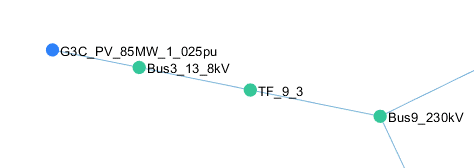
The Load-Flow Analyzer app also plots nodes and connections inside subsystems. For example, this figure shows a particular section of a model.
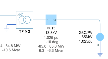
For this section of the model, this is the graph in the Graph tab of the Load-Flow Analyzer app.
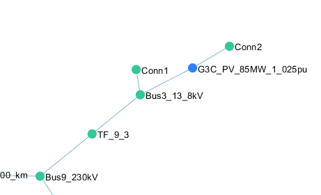
Now create a subsystem that comprises the Load Flow Source and Busbar blocks.

This figure shows the graph in the Graph tab of the Load-Flow Analyzer app after the subsystem creation.
Related Examples
Programmatic Use
Limitations
You cannot perform a load-flow analysis on a model if the model is not configured for such an analysis. For more information, see Perform a Load-Flow Analysis Using Simscape Electrical.
You cannot perform a load-flow analysis using the Load-Flow Analyzer app if the three-phase ports on relevant node or connection blocks in the model are expanded into separate phases. For more information, see Comparison of Three-Phase Port Types.
To obtain all the load-flow analysis results, you must put a Busbar or a Busbar (DC) block in the connection lines between each block.
You cannot alter the RLC structure of a constant impedance load from the app. To alter the structure, change the dropdown on the block mask.
If you parameterize your load-flow model using variables in the MATLAB base or model workspaces, the Load Flow Analyzer app evaluates these variables and provides the associated numeric values. If you then update the values of these variables inside the app, the numeric values replace the respective variable names in the block mask.
Version History
Introduced in R2020a
Select a Web Site
Choose a web site to get translated content where available and see local events and offers. Based on your location, we recommend that you select: United States.
You can also select a web site from the following list
Americas
- América Latina (Español)
- Canada (English)
- United States (English)
Europe
- Belgium (English)
- Denmark (English)
- Deutschland (Deutsch)
- España (Español)
- Finland (English)
- France (Français)
- Ireland (English)
- Italia (Italiano)
- Luxembourg (English)
- Netherlands (English)
- Norway (English)
- Österreich (Deutsch)
- Portugal (English)
- Sweden (English)
- Switzerland
- United Kingdom (English)