Contenido principal

radarTransceiver

Monostatic radar transceiver

Description

The radarTransceiver System object™ creates a monostatic radar object that generates I/Q samples of the received target echo. You can specify stationary or constant velocity point targets as tgt structs or you can define two-way propagation paths using the proppaths struct input argument. Alternatively, you can attach a radarTransceiver object as a sensor to a platform in a radarScenario to leverage built-in scenario, target, and trajectory management features. You can also create a radarTransceiver object that corresponds to your radarDataGenerator object.

To generate samples of the received target echo:

  1. Create the radarTransceiver object and set its properties.

  2. Call the object with arguments, as if it were a function.

To learn more about how System objects work, see What Are System Objects?

Creation

Description

radarTrans = radarTransceiver creates a monostatic radar object that generates I/Q samples of the received target echo using default narrowband transmit and receive antennas in a freespace propagation environment.

radarTrans = radarTransceiver(PropertyName=Value) creates a monostatic radar transceiver object with each specified PropertyName set to the corresponding Value. For example, you can specify the waveform using the Waveform property. You can specify additional pairs of arguments in any order as (PropertyName1=Value1, … ,PropertyNameN=ValueN).

example

iqSensor = radarTransceiver(radarGenerator) creates a corresponding radar transceiver, iqSensor, based on the radarDataGenerator object, radarGenerator. This syntax configures properties in iqSensor so that you can process the I/Q signals it generates to obtain comparable detections to those returned from radarDataGenerator.

Properties

expand all

Unless otherwise indicated, properties are nontunable, which means you cannot change their values after calling the object. Objects lock when you call them, and the release function unlocks them.

If a property is tunable, you can change its value at any time.

For more information on changing property values, see System Design in MATLAB Using System Objects.

Radar transmitter, specified as a phased.Transmitter object.

Radar transmit antenna, specified as either a phased.Radiator or phased.WidebandRadiator object. radarTransceiver only supports radiators with the Polarization property set to "None" or "Combined". "Dual" Polarization is not supported. To model polarization, you must set the polarization property in both the transmit and receive antenna objects to "Combined" and this also enables the sceneaxes input argument.

Radar receive antenna, specified as either a phased.Collector or phased.WidebandCollector. radarTransceiver only supports collectors with the Polarization property set to "None" or "Combined"."Dual" Polarization is not supported. To model polarization, you must set the polarization property in both the receive and transmit antenna objects to "Combined" and this also enables the sceneaxes input argument.

Radar receiver, specified as a phased.ReceiverPreamp or phased.Receiver object.

Radar mechanical scan mode, specified as one of the following:

  • "Circular" — The radar scans counter-clockwise in the azimuth plane. The azimuth plane is defined in the xy plane.

  • "Sector" — The radar scans back and forth within a sector in the azimuth plane, first in counter-clockwise direction, then in clockwise direction, and so on. The azimuth plane is defined in the xy plane.

  • "None" — The radar does not perform scanning.

Initial mechanical scan angle, specified as scalar. Units are in degrees (deg).

Dependencies

This property applies only when you set the MechanicalScanMode property to "Circular" or "Sector".

Data Types: double

Azimuth coverage limits for the mechanical scan sector, specified as a two-element row vector. The first element is the minimum azimuth and the second element is the maximum azimuth. Units are in degrees (deg).

Dependencies

To enable this property, set the MechanicalScanMode property to "Sector".

Data Types: double

Azimuth scan rate for the mechanical scan, specified as a positive scalar. Units are in degrees per second (deg/sec).

Dependencies

To enable this property set the MechanicalScanMode property to "Circular" or "Sector".

Data Types: double

Radar electronic scan mode, specified as one of the following:

  • "Sector" — The radar scan direction is determined by the scan rate specified in ElectronicScanRate and the elapsed time. If the ElectronicScanLimits is only along azimuth or elevation, the scan angle starts with the lower end of ElectronicScanLimits along that dimension and scans toward the upper end of the scan limit. When the scan reaches the upper end of ElectronicScanLimits, it restarts from the lower end of ElectronicScanLimits again. If ElectronicScanLimits is along both azimuth and elevation, the scan occurs along the longer dimension first and then moves to the next position in the shorter dimension.

  • "Custom" — The radar beam pointing direction and weights are determined by transmit and receive steering-related input arguments. The "Custom" selection enables wt, steert, wst, wr, steerr, and wsr input arguments.

  • "None" — The radar does not perform scanning.

Azimuth and elevation coverage limits for the electronic scan sector, specified as a 2-by-2 matrix. The first row specifies the scan coverage in the azimuth direction, where the first element is the minimum azimuth and the second element is the maximum azimuth. The second row specifies the scan coverage in the elevation direction, where the first element is the minimum elevation and the second element is the maximum elevation. Units are in degrees (deg).

Dependencies

To enable this property, set the ElectronicScanMode property to "Sector".

Data Types: double

Azimuth and elevation scan rates for the electronic scan, specified as a two-element column vector. The first element specifies the scan rate in the azimuth direction, and the second element specifies the scan rate in the elevation direction. Units are in degrees per second (deg/sec).

Dependencies

To enable this property, set the ElectronicScanMode property to "Sector".

Data Types: double

The mounting location is the offset between the radar mount origin and the origin of the platform, specified as a 3-element row vector in the form [x_offset y_offset z_offset], where x_offset, y_offset, and z_offset are offsets measured along the x-, y-, and z-axes. Units are in meters (m).

The mounting location defines the radar mounting frame origin (see Radar Coordinate Systems and Frames for more information on reference frames). The platform origin, which defines the platform body frame axes center, is a reference point in the radarTransceiver that is considered to be at [0 0 0] in Cartesian x, y, z coordinates. When the radarTransceiver is attached as a sensor to a platform in a radarScenario, the platform offset can be specified using the Dimensions property of the platfom object.

Data Types: double

Rotation angles of the radar transceiver mounting frame relative to the platform body frame, specified as a 3-element row vector of intrinsic Euler angles in the form [zyaw ypitch xroll], where zyaw, ypitch, and xroll are rotations measured about the z-, y-, and x-axes. Units are in degrees (deg).

Intrinsics rotations follow the right hand rule convention and are sequential:

  • zyaw, or yaw angle, rotates the mounting frame around the z-axis of the platform body frame.

  • ypitch, or pitch angle, rotates the mounting frame around the y-axis of the platform body frame. This rotation is relative to the mount orientation that results from the zyaw rotation.

  • xroll, or roll angle, rotates the mounting frame about the x-axis of the platform body frame. This rotation is relative to the mount orientation that results from the zyaw and ypitch rotations.

In other words, perform rotations in the order of yaw, pitch, and roll on the platform z-, y-, and x-axes to obtain the current mounting frame axes relative to the platform body frame. See Frame Rotation (Sensor Fusion and Tracking Toolbox) for more information on intrinsic rotations.

Mounting frame rotations are performed in the platform body frame and not the scenario frame defined by the sceneaxes input argument or the radarScenario global frame, if relevant. The platform body frame in the radarTransceiver is considered to follow the standard Cartesian orientation with x-, y-, and z-axes unrotated. When the radarTransceiver is attached as a sensor to a platform in a radarScenario, the platform orientation can be specified using the Orientation property of the platfom object.

Data Types: double

Source of number of pulses or sweeps in the signal, specified as one of the following:

  • "Property" — The number of pulses or sweeps in the signal is specified by the NumRepetitions property.

  • "Input port" — The number of pulses or sweeps in the signal is specified through the input argument N.

Number of pulses or sweeps in the signal, specified as a positive integer.

  • If you have a pulsed waveform object with multiple PRFs defined in the Waveform property, then NumRepetitions must be set equal to 1 unless you also specify the PRF index of the waveform, PRFIDX, as an input argument.

  • If you have a continuous waveform with multiple sweep times, then NumRepetitions must be set equal to 1.

Dependencies

To enable this property, set the NumRepetitionsSource property to its default value of "Property".

Data Types: double

Source of range limits, specified as "Property" or "Input port". When you set this property to "Property", the range limits are determined by the value of the RangeLimits property. When you set this property to "Input port", the range limits are determined by the input argument rl.

Data Types: char | string

Minimum and maximum range limits of interest for the received signal, specified as a 2-element row vector, where the first element is the minimum range limit and the second element is the maximum limit. The default value of [0 inf] indicates that all ranges are of interest. Units are in meters (m).

Range limits are used to compute the signal arrival time interval, similar to a range gate. Only the signal within the time interval of interest is returned. A signal from a range beyond the maximum unambiguous range will only be returned if its apparent unambiguous arrival time is within the interval of interest.

Example: [1000 10000]

Tunable: Yes

Dependencies

To enable this property, set the RangeLimitsSource property to Property.

Data Types: double

Set this property to true to enable the output of corresponding ranges for the radar signal. You must also specify the output argument rgrid to return the range grid of the received signal.

Data Types: logical

Set this property to true to enable the output corresponding times for the radar signal. You must also specify the output argument tgrid to return the time grid of the received signal.

Data Types: logical

Usage

Description

sig = radarTrans(proppaths,t) returns I/Q samples of the target echo received at the radar sig at time t (in seconds) due to the propagation paths specified in proppaths. This is the recommended syntax.

example

sig = radarTrans(tgt,t) returns I/Q samples of the target echo received at the radar sig, at time t seconds due to targets specified by tgt in a freespace propagation environment. This syntax is intended for use only when radarTransceiver is advanced by consecutive time steps (t is set equal to the start time of the next available repetition interval, see info).

example

[___,rgrid] = radarTrans(___) also returns the range grid rgrid of the received signal.

To enable this syntax, set the RangeOutputPort property to true.

example

[___,tgrid] = radarTrans(___) also returns the time grid tgrid of the received signal.

To enable this syntax, set the TimeOutputPort property to true.

[___,info] = radarTrans(___) also returns additional simulation metadata in the structure info.

example

You can combine optional output arguments when you set the properties to enable them. You must list optional outputs in the same order as the enabled properties. The info argument must be listed last.

[___] = radarTrans(___,sceneaxes) specifies the scenario axes sceneaxes.

To enable this syntax, set the Polarization property in the TransmitAntenna and ReceiveAntenna objects to "Combined".

[___] = radarTrans(___,N) specifies the number of pulses/sweeps N in the signal as a positive integer.

To enable this syntax, set the NumRepetitionSource to "Input port".

[___] = radarTrans(___,PRFIDX) specifies the PRF index of the radar waveform as a positive integer.

To enable this syntax, set the PRFSelectionInputPort property to true within the waveform object specified by the Waveform property.

[___] = radarTrans(___,wt) specifies the transmit weights of the radar system as a column vector.

To enable this syntax, set the ElectronicScanMode property to "Custom" and also set the WeightsInputPort property to true in the transmit antenna object specified by the TransmitAntenna property.

[___] = radarTrans(___,steert) specifies the transmit steering angle azimuth and elevation as a column vector.

To enable this syntax, set the ElectronicScanMode property to "Custom", specify the transmit antenna object as a senor with subarrays in the TransmitAntenna property, and set the subarray's SubarraySteering property to "Phase" or "Time".

[___] = radarTrans(___,wst) specifies the transmit weights applied to each element as either a matrix or a cell array.

To enable this syntax, set the ElectronicScanMode property to "Custom", specify the transmit antenna object as a senor with subarrays in the TransmitAntenna property, and set the subarray's SubarraySteering property to "Custom".

[___] = radarTrans(___,wr) specifies the receive weights of the radar system as a column vector.

To enable this syntax, set the ElectronicScanMode property to "Custom" and also set the WeightsInputPort property to true in the receive antenna object specified by the ReceiveAntenna property.

[___] = radarTrans(___,steerr) specifies the receive steering angle azimuth and elevation as a column vector.

To enable this syntax, set the ElectronicScanMode property to "Custom", use a subarray in the receive antenna, and set its SubarraySteering property to "Phase" or "Time".

[___] = radarTrans(___,wsr) specifies the receive weights applied to each element as either a matrix or a cell array.

To enable this syntax, set the ElectronicScanMode property to "Custom", specify the receive antenna object as a senor with subarrays in the ReceiveAntenna property, and set the subarray's SubarraySteering property to "Phase" or "Time".

[___] = radarTrans(___,rl) specifies the range limits of interest.

To enable this syntax, set the RangeLimits property to "Input port".

You can combine optional input arguments when you set the properties to enable them. You must list optional inputs in the same order as the enabled properties and in the order the syntaxes are listed for properties that enable multiple input arguments.

Input Arguments

expand all

Current time at which the radar receives the target echo, specified as a nonnegative scalar in units of seconds (s). The current time must be greater than or equal to the start time of the next available repetition interval NextRepetitionTime, which is a field in the output structure info. In other words, the radar cannot go back in time.

Data Types: double

Monostatic two-way propagation paths that may include target interactions, specified as an array of structs. You can use the propagation paths returned by freeSpacePath for this input argument.

When radarTransceiver is attached to a platform as a sensor in a radarScenario, propagation paths are defined in the scenario.

Each structure describes a propagation path between the transmit and the receive antenna of the radar transceiver, and contains the following required fields:

FieldDescription
PathLengthPropagation path length, specified as a positive scalar in units of meters (m).
PathLossPropagation path loss, specified as a scalar in units of decibels (dB).
ReflectionCoefficient

Cumulative reflection coefficient for all reflections along the path, specified as a scalar in linear units. Reflections along the path might include contributions from scatterers or targets.

If the TransmitAntenna and ReceiveAntenna antennas are polarized (Polarization property in the TransmitAntenna and ReceiveAntenna objects are set to "Combined"), the ReflectionCoefficient must be specified as a 3-by-3 matrix representing how the transmit signal components along each coordinate system axis of the scene is mapped to the components of the received signal. The reflection coefficient is specified in the scenario frame set by the sceneaxes input argument.

AngleOfDeparturePropagation path angle of departure, specified as a two-element column vector in the form of [azimuth; elevation] in units of degrees (deg). The transmit antenna angle of departure is measured with respect to the radar transceiver mounting frame.
AngleOfArrivalPropagation path angle of arrival, specified as a two-element column vector in the form of [azimuth; elevation] in units of degrees (deg). The receive antenna angle of arrival is measured with respect to the radar transceiver mounting frame.
DopplerShiftCumulative Doppler shift along the path, specified as a scalar in units of hertz (Hz).

When the proppaths struct is empty, receiver noise is returned by sig.

Data Types: struct

Target that reflects the radar signal, specified as an array of structs.

This input argument is intended for use only when radarTransceiver is advanced by consecutive time steps (t is set equal to the start time of the next available repetition interval). When t is set to a value that is greater than the NextRepetitionTime filed in info, potential returns from targets that fall beyond the maximum unambiguous range of the previous PRI could appear in the next PRI.

When radarTransceiver is attached to a platform as a sensor in a radarScenario, target properties are defined in the scenario.

All target coordinates are defined with respect to the platform body frame. The platform origin, which defines the platform body frame axes center, is a reference point in the radarTransceiver that is considered to be at [0 0 0] in unrotated x, y, z Cartesian coordinates.

Each structure describes a point target and contains the following fields:

FieldDescription
Position

Position of the target, specified in the platform body frame as a 3-element row vector in the form of [x y z]. Units are in meters (m). This is a required field and there is no default value.

Velocity

Velocity of the target, specified in the platform body frame as a 3-element row vector in the form of [x y z]. Units are meters per second (m/s). The default value is [0 0 0].

Orientation

Orientation of the target with respect to the platform body frame, specified as a scalar quaternion or a 3-by-3 real-valued orthonormal frame rotation matrix in units of degrees (deg). Orientation defines the intrinsic frame rotation from the platform body frame to the current target frame. The default value is quaternion(1,0,0,0).

Signatures

Mean monostatic target radar cross section (RCS) signature, specified as a cell array of platform signature objects or structs. If there are multiple cells, radarTransceiver selects the first rcsSignature object and any other signature objects are ignored. The default value is a cell array containing an rcsSignature object with property values that depend on polarization. rcsSignature objects support polarized and nonpolarized targets, but a struct is only available if polarization is not considered.

For the nonpolarized case, the default value is a cell array containing an rcsSignature object with default property values. If the transmit and receive antennas are polarized, the default value is a cell array containing an rcsSignature object with the EnablePolarization property set to true and default values for other properties. See below for more information.

The expected value of the Signatures field depends on polarization:

  • If polarization is not considered (Polarization property in the TransmitAntenna and ReceiveAntenna objects are set to "None"):

    • The default Signatures field is cell array containing an rcsSignature object with default values including that the EnablePolarization property is set to false.

    • If Signatures is specified as an rcsSignature object, the EnablePolarization property of the rcsSignature object must be set to false.

    • If Signatures is specified as a struct, an rcsSignature object will be generated from the struct using the following required fields:

      • Pattern — Specify the target's RCS pattern (in dBm) as either a P-by-Q matrix or a P-by-Q-by-K array. If defined as a P-by-Q-by-K array, each entry in the array specifies the RCS at the corresponding frequency and the corresponding (azimuth, elevation) direction. If defined as a P-by-Q matrix, then the pattern applies to all frequencies. The default is [0 0;0 0].

      • Azimuth — Specify the azimuth angles (in degrees) at which the RCS pattern is sampled as a length-Q vector. The default is [-180 180].

      • Elevation — Specify the elevation angles (in degrees) at which the RCS pattern is sampled as a length-P vector. The default is [-90; 90].

      • Frequency — Specify the frequencies (in Hz) at which the RCS pattern is sampled as a length-K vector. The default is [0 1e20].

  • If polarization is considered (Polarization property in the TransmitAntenna and ReceiveAntenna objects are set to "Combined"):

    • The default Signatures field is cell array containing an rcsSignature object with the default values except that the EnablePolarization property is set to true.

    • Signatures is specified as an rcsSignature object and the EnablePolarization property must be set to true.

Example: tgt1 = struct("Position",[0 5e3 0],"Velocity",[0 0 0]);tgt2 = struct("Position",[10e3 0 0],"Velocity",[0 0 0]);tgt = [tgt1 tgt2];

Data Types: struct

Scenario frame orientation used for polarization orientation, specified as a 3-by-3 orthogonal frame rotation matrix that rotates in units of degrees (deg). Orientation defines the intrinsic frame rotation from the platform body frame to the current scenario frame. See Frame Rotation (Sensor Fusion and Tracking Toolbox) for more information.

Dependencies

To enable this input argument, set the Polarization property in the TransmitAntenna and ReceiveAntenna objects to "Combined".

Data Types: double

Number of pulses/sweeps in the signal, specified as a positive integer.

  • If you have a pulsed waveform object with multiple PRFs defined in the Waveform property, then N must be set equal to 1 unless you also specify the PRF index of the waveform, PRFIDX, as an input argument.

  • If you have a continuous waveform with multiple sweep times, then N must be set equal to 1.

Dependencies

To enable this input argument, set the NumRepetitionSource property to "Input port".

Data Types: double

PRF index of the radar waveform, specified as a positive integer.

Dependencies

To enable this input argument, set the PRFSelectionInputPort property to true in the waveform object specified by the Waveform property.

Data Types: double

Transmit weights of the radar system, specified as a column vector.

If a regular antenna array is used to transmit, wt is of length NTE, where NTE is the number of antenna elements in the transmit antenna array.

If a subarray is used to transmit, wt is of length NTS, where NTS is the number of subarrays in the transmit antenna array.

Dependencies

To enable this input argument, set the ElectronicScanMode property to "Custom" and set the WeightsInputPort property to true in the transmit antenna objected specified by the TransmitAntenna property.

Data Types: double

Transmit steering angle, specified as a 2-element column vector in the form of [azimuth; elevation], in units of degrees (deg).

Dependencies

To enable this input argument, set the ElectronicScanMode property to "Custom". Use a subarray in the transmit antenna, and set its SubarraySteering property to "Phase" or "Time".

Data Types: double

Transmit weights applied to each element, specified as either a matrix or a cell array.

If the transmit antenna uses a:

  • phased.ReplicatedSubarray, wst must be an NTE-by-NTS matrix, where NTE is the number of elements in each individual subarray and NTS is the number of subarrays. Each column in wst specifies the weights for the elements in the corresponding subarray.

  • phased.PartitionedArray and its individual subarrays have the same number of elements, wst must be an NTE-by-NTS matrix, where NTE is the number of elements in each individual subarray and NTS is the number of subarrays. Each column in wst specifies the weights for the elements in the corresponding subarray.

  • phased.PartitionedArray and its subarrays can have different number of elements, wst can be one of the following:

    • NTE-by-NTS matrix, where NTE indicates the number of elements in the largest subarray and NTS is the number of subarrays.

      If wst is a matrix, the first KT entries in each column, where KT is the number of elements in the corresponding subarray, specify the weights for the elements in the corresponding subarray.

    • 1-by-NTS cell array, where NTS is the number of subarrays and each cell contains a column vector whose length is the same as the number of elements of the corresponding subarray.

Dependencies

To enable this input argument, set the ElectronicScanMode property to "Custom", specify the transmit antenna object as a senor with subarrays in the TransmitAntenna property, and set the subarray's SubarraySteering property to "Custom".

Data Types: double

Receive weights of the radar system, specified as a column vector. If a regular antenna array is used to receive, wr is of length NRE, where NRE is the number of antenna elements in the receive antenna array. If a subarray is used to receive, wr is of length NRS, where NRS is the number of subarrays in the receive antenna array.

Dependencies

To enable this input argument, set the ElectronicScanMode property to "Custom" and set the WeightsInputPort property to true in the transmit antenna objected specified by the ReceiveAntenna property.

Data Types: double

Receive steering angle in degrees, specified as a 2-element column vector in the form of [azimuth; elevation].

Dependencies

To enable this input argument, set the ElectronicScanMode property to "Custom". Use a subarray in the receive antenna, and set its SubarraySteering property to "Phase" or "Time".

Data Types: double

Receive weights applied to each element, specified as either a matrix or a cell array.

If the receive antenna uses a:

  • phased.ReplicatedSubarray object, wsr must be an NRE-by-NRS, matrix where NRE is the number of elements in each individual subarray and NRS is the number of subarrays. Each column in wsr specifies the weights for the elements in the corresponding subarray.

  • phased.PartitionedArray object, and its individual subarrays have same number of elements, wsr must be an NRE-by-NRS matrix, where NRE is the number of elements in each individual subarray and NRS is the number of subarrays. Each column in wsr specifies the weights for the elements in the corresponding subarray.

  • phased.PartitionedArray object, and its subarrays can have different number of elements, wsr can be one of the following:

    • NRE-by-NRS matrix, where NRE indicates the number of elements in the largest subarray and NRS is the number of subarrays.

      If wsr is a matrix, the first KR entries in each column, where KR is the number of elements in the corresponding subarray, specify the weights for the elements in the corresponding subarray.

    • 1-by-NRS cell array, where NRS is the number of subarrays and each cell contains a column vector whose length is the same as the number of elements of the corresponding subarray.

Dependencies

To enable this input argument, set the ElectronicScanMode property to "Custom", specify the receive antenna object as a senor with subarrays in the TransmitAntenna property, and set the subarray's SubarraySteering property to "Custom".

Data Types: double

Minimum and maximum range limits of interest for the received signal, specified as a 2-element row vector, where the first element is the minimum range limit and the second element is the maximum limit. The default value of [0 inf] indicates that all ranges are of interest. Units are in meters.

Range limits are used to compute the signal arrival time interval, similar to a range gate. Only the signal within the time interval of interest is returned. A signal from a range beyond the maximum unambiguous range will only be returned if its apparent unambiguous arrival time is within the interval of interest.

Dependencies

To enable this input argument, set the RangeLimitsSource property to "Input port".

Data Types: double

Output Arguments

expand all

I/Q signal received at the radar receiver, returned as a one of the following:

  • NS-by-NRE-by-N array — If the radar uses a regular antenna array for receiving, the dimension of sig is NS-by-NRE-by-N, where NRE is the number of antenna elements in the receive antenna array, NS is the number of samples in each transmitted pulse/sweep, and N is the number of transmitted pulses/sweeps.

  • NS-by-NRS-by-N array — If the radar uses a subarray for receiving, the dimension of sig is NS-by-NRS-by-N, where NRS is the number of subarrays in the receive antenna array.

N is the number of pulses or sweeps specified by the value of the NumRepetition property or the input argument N. When multiple pulses/sweeps are simulated, the targets are assumed to move according to a constant-velocity trajectory.

Data Types: double
Complex Number Support: Yes

Range grid of received signal, returned as an NSRL-by-1 real vector or cell array. Units are in meters (m).

  • If y is an array, rgrid is an NSRL-by-1 vector.

  • If y is a cell array, rgrid is also a cell whose cells contain the range grids of the corresponding signal in y.

Dependencies

To enable this output argument, set the RangeOutputPort property to true.

Data Types: double

Time grid of received signal, returned as an NSRL-by-1 real vector or cell array. Units are in seconds (s).

  • If y is an array, tgrid is an NSRL-by-1 vector.

  • If y is a cell array, tgrid is also a cell whose cells contain the time grids of the corresponding signal in sig.

Dependencies

To enable this output argument, set the TimeOutputPort property to true.

Data Types: double

Simulation metadata, returned as a struct containing the following fields:

FieldDescription
IsScanDoneWhether one period of the mechanical scan is done, returned as a logical false (0) or true (1).
MechanicalAngleCurrent antenna pointing angle due to mechanical scan, returned as a scalar in units of degrees (deg).
ElectronicAngleCurrent antenna pointing angle due to electronic scan, returned as a scalar in units of degrees (deg).
OriginRadar mounting location origin with respect to the platform body frame, returned as 3-element row vector in the form [x y z].
OrientationOrientation of the radar mounting frame with respect to the platform body frame, returned as a 3-by-3 real-valued orthonormal frame rotation matrix, in units of degrees (deg). Orientation defines the intrinsic frame rotation from the platform body frame to the current radar mounting frame.
NextRepetitionTime

Start time of the next available repetition interval, in units of seconds (s). The value of NextRepetitionTime depends on the type of waveform set in the Waveform property:

  • For pulsed waveforms, NextRepetitionTime is equal to t + 1/PRF * Num_Reps, where t is the current time, 1/PRF is the waveform PRI, and Num_Reps is the number of pulses set by the NumRepetitions property or the input argument N.

  • For continuous waveforms, NextRepetitionTime is equal to t + SweepTime * Num_Reps, where t is the current time, SweepTime is the waveform sweep duration, and Num_Reps is the number of sweeps set by the NumRepetitions property or the input argument N.

Data Types: struct

Object Functions

To use an object function, specify the System object as the first input argument. For example, to release system resources of a System object named obj, use this syntax:

release(obj)

expand all

configureAntennasConfigure radarTransceiver transmit and receive antennas
stepRun System object algorithm
releaseRelease resources and allow changes to System object property values and input characteristics
resetReset internal states of System object

Examples

collapse all

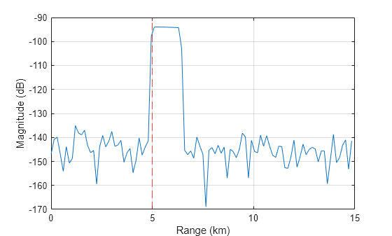
Calculate the free space propagation path for a radar transceiver configuration.

Create a radar transceiver with an isotropic antenna, transmitting a linear frequency modulated (LFM) pulse waveform with a 10 microsecond pulse width. Calculate the free space propagation paths assuming the radar is at the origin and the target is 5 km away. Return I/Q signals from the radar transceiver at the initial time and plot the results. Start by initializing the radar transceiver.

wav  = phased.LinearFMWaveform(PulseWidth=1e-5);
ant  = phased.IsotropicAntennaElement;
rdr  = radarTransceiver(Waveform=wav, ...
     TransmitAntenna=phased.Radiator(Sensor=ant), ...
     ReceiveAntenna=phased.Collector(Sensor=ant), ...
     RangeOutputPort=true);
freq = rdr.TransmitAntenna.OperatingFrequency; 

Define the radar position, target position, and target velocity. Calculate the free space propagation paths. The target is located 5 km away and is moving at 20 m/s in the y-direction.

rdrPose.Position = [0 0 0];   % Radar position (m)
tgtPose.Position = [0 5e3 0]; % Target position (m)
tgtPose.Velocity = [0 20 0];  % Target velocity (m/s) 
proppaths        = freeSpacePath(freq,rdrPose,tgtPose)
proppaths = struct with fields:
               PathLength: 10000
                 PathLoss: 191.9392
    ReflectionCoefficient: 11.2177
         AngleOfDeparture: [2×1 double]
           AngleOfArrival: [2×1 double]
             DopplerShift: -40.0277

Return I/Q signals from the radarTransceiver at a time of 0 seconds and plot the results. The target is located at 5 km.

t = 0; % Time (sec) 
[iq,rgrid] = rdr(proppaths,t);

% Plot 
figure
plot(rgrid*1e-3,mag2db(abs(sum(iq,2))))
grid on
hold on
xline(5,'r--')
xlabel('Range (km)')
ylabel('Magnitude (dB)')

Figure contains an axes object. The axes object with xlabel Range (km), ylabel Magnitude (dB) contains 2 objects of type line, constantline.

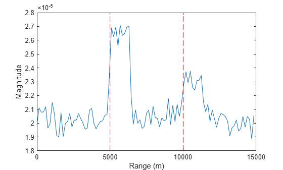
Model the target echo received by a monostatic radar using the radarTransceiver object.

Create the radar targets as an array of two structures with a specified position and velocity.

tgt1 = struct( ...
    'Position', [0 5e3 0], ...
    'Velocity', [0 0 0]);
tgt2 = struct( ...
    'Position', [10e3 0 0], ...
    'Velocity', [0 0 0]);

Create a surveillance radar 15 meters above the ground. Specify rpm to determine the scan rate (in deg/s). For the specified scanrate and beamwidth, determine the update rate.

rpm = 12.5;
scanrate = rpm*360/60;       % deg/s
beamw = 1;                   % beamwidth
updaterate = scanrate/beamw; % update at each beam
radarht = 15.0;              % radar height

Create a phased.CustomAntennaElement object that acts as a transmit antenna element and a receive antenna element in the radarTransceiver object.

az = -180:0.5:180;
el = -90:0.5:90;
pat = zeros(numel(el),numel(az));
pat(-0.5 <= el & el <= 0.5,-0.5 <= az & az <= 0.5) = 1;
ant = phased.CustomAntennaElement('AzimuthAngles',az,...
    'ElevationAngles',el,'MagnitudePattern',mag2db(abs(pat)),...
    'PhasePattern',zeros(size(pat)));

Create a radarTransceiver object. Specify a rectangular waveform for the radar using the phased.RectangularWaveform object. Specify the transmit antenna and the receive antenna. The mechanical scan mode is set to 'Circular' with a defined scan rate.

wav = phased.RectangularWaveform('PulseWidth',1e-5);
sensor = radarTransceiver( ...
    'Waveform',wav, ...
    'TransmitAntenna',phased.Radiator('Sensor',ant), ...
    'ReceiveAntenna',phased.Collector('Sensor',ant), ...
    'MechanicalScanMode','Circular', ...
    'MechanicalScanRate',scanrate, ...
    'MountingLocation',[0,0,radarht]);

Generate detections from a full scan of the radar.

simTime = 0;
sigi = 0;
while true
    [sig, info] = sensor([tgt1 tgt2], simTime);
    sigi = sigi + abs(sig);

    % Is full scan complete?
    if info.IsScanDone
        break % yes
    end
    simTime = simTime + 1/updaterate;
end
r = (0:size(sigi,1)-1)/sensor.Waveform.SampleRate* ...
    sensor.TransmitAntenna.PropagationSpeed/2;
plot(r,sigi)
hold on
plot([5e3 5e3],ylim,'r--',[10e3 10e3],ylim,'r--')
xlabel('Range (m)')
ylabel('Magnitude')

Figure contains an axes object. The axes object with xlabel Range (m), ylabel Magnitude contains 3 objects of type line.

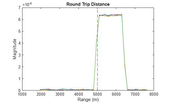
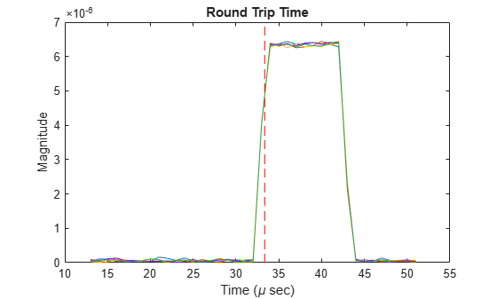
Find the received signals at a monostatic radar between 4 and 6 km from target.

First, create a target at a range of 5 km moving at 10 m/sec.

rng1 = 5e3;
tgt = struct( ...
    'Position',[0 rng1 0], ...
    'Velocity',[0 10 0]);

Create a rectangular pulse transmitted waveform.

wav = phased.RectangularWaveform('PulseWidth',1e-5);

Configure the radarTransceiver. The transmit and receive arrays are co-located 5-element ULAs. Configure the radarTransceiver to output the range and time.

ant = phased.IsotropicAntennaElement;
array = phased.ULA(5,Element=ant);
sensor = radarTransceiver(...
    Waveform=wav, ...
    TransmitAntenna=phased.Radiator('Sensor',array), ...
    ReceiveAntenna=phased.Collector('Sensor',array), ...
    MechanicalScanMode='None', ...
    RangeLimits=[2e3 6e3], ...
    RangeOutputPort=true, ...
    TimeOutputPort=true);

Generate the received signal.

simTime = 0;
[sig,rgrid,tgrid,info] = sensor(tgt,simTime);

Plot the signal versus range and time.

plot(rgrid,abs(sig))
hold on
plot([rng1 rng1],ylim,'r--')
title('Round Trip Distance')
xlabel('Range (m)')
ylabel('Magnitude')
hold off

Figure contains an axes object. The axes object with title Round Trip Distance, xlabel Range (m), ylabel Magnitude contains 6 objects of type line.

plot(tgrid*10^6,abs(sig))
hold on;
title('Round Trip Time')
xlabel('Time (\mu sec)')
ylabel('Magnitude')
c = physconst('LightSpeed');
tarrive = 2*rng1/c*1e6;
plot([tarrive tarrive],ylim,'r--')

Figure contains an axes object. The axes object with title Round Trip Time, xlabel Time ( mu sec), ylabel Magnitude contains 6 objects of type line.

Create a radarDataGenerator and generate a radar transceiver from it.

rdr = radarDataGenerator;
iqsensor = radarTransceiver(rdr);

Produce radar signal from a target using the transceiver.

tgt = struct('Position',[50e3 0 0]);
x = iqsensor(tgt,0);
t = (0:numel(x)-1)/iqsensor.Waveform.SampleRate;
plot(t*physconst('lightspeed')/2,abs(x))
xlabel('Range (m)')
ylabel('Magnitude')

Figure contains an axes object. The axes object with xlabel Range (m), ylabel Magnitude contains an object of type line.

References

[1] M. Richards. "Fundamentals of Radar Signal Processing, 2nd ed." McGraw-Hill Professional Engineering, (2014).

Extended Capabilities

expand all

C/C++ Code Generation
Generate C and C++ code using MATLAB® Coder™.

Version History

Introduced in R2021a

expand all